A portable hydraulic unit must deliver the required flow and pressure while surviving movement, vibration, heat, lifting, and field maintenance. By the end, you will know what data to provide, how engineers size the power and mobility systems, what a useful CAD package contains, and which validation records to demand before production.
Key takeaways
- Freeze duty, environment, handling, and maintenance requirements before selecting components.
- Size pump flow, pressure, reservoir, valves, and cooling around the actual duty cycle.
- Use 3D models and 2D drawings to catch access, hose, and assembly conflicts.
- Validate the complete unit before releasing controlled drawings and bills of materials.
Define the unit around duty, environment, and handling
Do not start with a pump catalogue. Before portable mobile hydraulic power unit design begins, freeze the work the unit must perform, the conditions it will face, and how people will move and maintain it.
1. Define duty: required flow in L/min, normal and peak pressure in bar, actuator speed, cycle timing, simultaneous functions, continuous run time, oil temperature range, and acceptable pressure drop. Base cooler sizing on the worst sustained cycle, because heat comes from input power minus useful hydraulic output plus losses—not from peak flow alone.
2. Define the power source: available voltage and phase, motor or engine power, battery capacity and run time, starting current, fuel limits, noise limit, and control voltage.
3. Define the environment: ambient temperature, operating altitude, dust, water exposure, corrosion risk, ventilation, and the required protection for hot surfaces, electrical parts, hoses, and stored pressure.
4. Define handling: overall envelope, mass, centre of gravity, wheel or axle loads, slope, lifting points, tie-down locations, vibration and transport loads, and access for filters, valves, gauges, and hose replacement.
Specify the complete system—prime mover, pump, reservoir, filtration, relief valve, valves, cooler, accumulator, gauges, hoses, battery, frame, wheels, and enclosure. Apply ISO 4413:2010 to design and maintenance, then use the iterative hazard process in ISO 12100 to address unexpected movement, hose rupture, lifting, transport, and service access before the enclosure is finalized.
Move from duty requirements to a correctly sized hydraulic circuit
Convert the actuator’s required force and speed into pressure and flow before selecting hardware. Use hydraulic power ≈ pressure (bar) × flow (L/min) ÷ 600 kW, then divide by the combined pump, drive, and control efficiency.
Select the motor or engine from shaft power, including cold-start viscosity and pressure-compensated standby losses; nominal hydraulic power alone can produce an overheated or non-starting prime mover.
Translate the result into a circuit with these checks:
- Calculate pump displacement from required flow, shaft speed, and volumetric efficiency, then verify peak pressure against the pump’s continuous rating.
- Size the reservoir for usable oil volume, deaeration, expansion, and return flow; calculate suction and return pressure losses at the smallest hose diameter.
- Select the relief valve, directional or proportional valve, filtration, gauges, and cooler from actual flow and pressure-drop data, not port size alone.
- Base cooler capacity on worst sustained duty: shaft input minus useful hydraulic output and component losses. Peak flow alone can undersize cooling in hot ambient conditions.
- If an accumulator is present, specify its type, volume, gas precharge, compatible fluid-side parts, isolation valve, controlled discharge path, warning label, and maintenance instruction.
Hydraulic power pack product development then turns the schematic into a testable circuit. Review stored pressure, hose rupture, unexpected movement, hot surfaces, electrical hazards, lifting, and service access through the iterative risk process in ISO 12100.
Review installation, commissioning, operation, maintenance, and disposal against ISO 4413:2010, then define pressure, flow, temperature, leakage, noise, and endurance tests before building the prototype.
Choose the drive, mobility system, and protection for the site
Choose the prime mover and mobility system together: a 30 kW hydraulic demand is not a 30 kW motor selection once pump, coupling, valve, and cold-fluid losses are included. Size the drive for shaft power at the worst sustained duty, then check starting torque, standby heating, and available energy.
| Option | Strength | Disqualifier or design check |
|---|---|---|
| Electric motor | Clean, quiet, and suitable for indoor or fixed electrical supply | Verify voltage, phase, starting current, enclosure rating, cable length, and heat rejection |
| Engine-driven | Independent of grid power and suitable for remote, high-duty work | Account for fuel, exhaust, noise, vibration, cooling-air clearance, and service access |
| Battery-electric | Zero local exhaust and flexible indoor operation | Calculate battery capacity from pressure-flow duty, motor efficiency, run time, ambient temperature, and recharge time |
| Casters | Easy positioning on smooth floors | Reject for loose ground, slopes, towing, or high hose-pull loads; include wheel brakes |
| Tyres | Better shock absorption and ground clearance | Check axle load, steering, parking brake, and stability on the actual terrain |
| Skid or trailer chassis | Skids suit lifting and fixed placement; trailers suit road-towed mobility | Provide rated lifting points, tie-downs, axle and hitch ratings, lights, brakes, and legal road equipment |
Protect the selected arrangement against the site, not an ideal workshop. Apply ISO 12100 risk assessment to stored pressure, unexpected movement, hot surfaces, hose rupture, lifting, and maintenance access; use guards, hose restraint, pressure-release points, emergency stopping, and weather protection. Review the complete installation against ISO 4413 before release.
Use 3D and 2D engineering data to prevent assembly and service failures
A 3D model prevents failures that a rendered image cannot reveal: interference, unreachable fittings, incorrect component clearances, poor hose routing, and an unstable centre of gravity. Treat 3D modeling hydraulic equipment as an engineering control, not a presentation exercise. Link the assembly to a controlled bill of materials, interface dimensions, revision history, and drawing-release process.
Check the model with every part installed, including seals, adapters, fasteners, gauges, test points, guards, covers, batteries, and drain paths. Route each hose using the manufacturer’s minimum bend radius at the fitting, while allowing for pressure, motion, temperature, impulse duty, and assembly tolerance.
Confirm access for filter changes and valve removal with the unit fully assembled. Check lifting points, component retention, frame strength, wheel loads, and transport vibration.
The 2D design hydraulic power unit package must define the manufacturing and inspection information that CAD geometry leaves ambiguous:
- Datums, critical dimensions, geometric tolerances, surface finishes, and hole sizes
- Weld symbols, weld sizes, material grades, and post-weld requirements
- Every port’s thread standard, size, sealing method, orientation, and pressure-test requirement
- Hose lengths, end fittings, bend limits, clamps, and routing references
- Inspection points, acceptance criteria, test pressures, and revision status
- Interface dimensions for the frame, enclosure, lifting equipment, and customer connections
Use ISO 4413:2010 as the system-level safety reference, then release only matched models, drawings, bills of materials, and revisions. Similar-looking parts are not interchangeable.
Validate the complete unit and control its release to production
A CAD assembly proves that parts fit in space; it does not prove that the unit is safe, manufacturable, or capable of its duty.
Product development 3D modeling for portable mobile hydraulic power units must therefore be separated from engineering validation: modelling checks interfaces, clearances, routing, and access, while validation checks pressure, flow, heat, stability, stored energy, controls, and performance under the defined duty cycle.
Expect a development partner to provide:
- A released 3D assembly linked to a controlled bill of materials, including seals, adapters, fasteners, test points, drain paths, and service clearances.
- 2D manufacturing drawings with datums, tolerances, surface finishes, weld details, port callouts, inspection points, and revision status.
- Hydraulic schematics, component data sheets, interface dimensions, hose and tube schedules, and an accumulator record covering volume, gas precharge, isolation, and safe discharge.
- A validation plan and test report covering leakage, pressure, flow, noise, thermal performance at worst sustained duty, emergency stopping, mobility, lifting, and guarding against ISO 4413:2010 requirements.
- A nonconformance log, corrective-action record, updated risk assessment, and signed production-release package identifying superseded files.
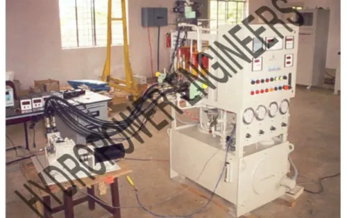
Hydropower Engineers can be evaluated on whether its design process produces this evidence, not merely a convincing render. Release only the configuration whose drawings, bill of materials, test results, software or control settings, and maintenance instructions share the same revision. Turning off the pump does not make an accumulator-fed circuit safe.
Related products
 | Portable Mobile Hydraulic Power Unit Portable Mobile Hydraulic Power Unit Power your operations anywhere with the Portable Power Unit from Hydropower Engineering Systems, a highly efficient mobile hydraulic power solution... View product → |
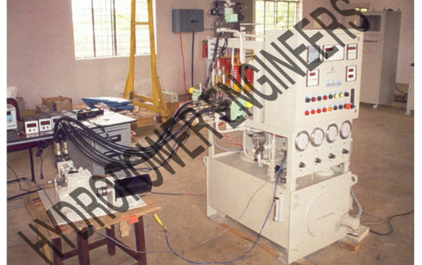 | Hydraulic Power Pack Hydropower Engineering Systems offers high-performance Hydraulic Power Packs designed to meet a wide range of industrial application requirements... View product → |
Frequently asked questions
What should you define before starting portable mobile hydraulic power unit design?
Define the actuator duty, required pressure and flow, operating cycle, ambient conditions, contamination exposure, noise limits, lifting or rolling method, service access, and connection points.
How do you size a hydraulic circuit for a portable power unit?
Convert actuator force and speed into pressure and flow requirements, then select the pump, motor, reservoir, valves, filtration, cooling, and hoses for the duty cycle rather than catalogue ratings alone.
What should 3D modeling cover in hydraulic equipment development?
Model the frame, motor, pump, manifold, reservoir, guards, wheels, hoses, connectors, lifting points, and service clearances so interference and access problems appear before fabrication.
Why are 2D drawings still needed for a hydraulic power unit?
2D drawings define dimensions, tolerances, hole patterns, weld details, interfaces, hose connections, and inspection points that manufacturers and service teams need after the 3D model is complete.