A tube expanding machine can show the correct hydraulic pressure and still produce a defective tube-to-tubesheet joint. You will be able to map the test sequence, select the right sensors and fixtures, separate pressure, force, dimensional and endurance checks, and specify a defensible test record for work carried out in Chennai.
Key takeaways
- Rate every hose, coupler, gauge and fixture above proof pressure.
- Measure actuator pressure, piston area, force and tube movement together.
- Separate machine, joint and finished-tube tests in the test plan.
- Record calibration, pressure hold time, leakage and final inspection results.
What the hydraulic test sequence checks first
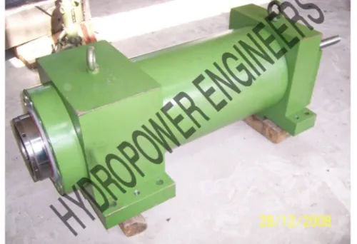
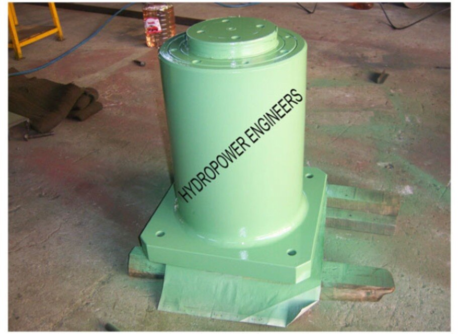
Mount the tube expanding machine, or its test cylinder, to a rigid fixture rated above the planned proof pressure. Connect the pressure line to the actuator inlet and the return line to the reservoir, then confirm that every hose, quick coupler, manifold, gauge, seal, and fixture is rated for the test pressure.
1. Fill the circuit with the specified hydraulic fluid and bleed air at the highest points. Trapped air can compress, create a false pressure drop, and make the actuator move unpredictably.
2. Set the relief valve below the maximum working pressure of the lowest-rated component, not below the machine’s nominal rating alone. Lock the setting and record it.
3. Check for leakage at fittings and seals at low pressure before increasing pressure in controlled steps.
4. Set the commanded expansion force or pressure, run the expansion stroke, hold it for the specified duration, and record starting pressure, pressure-versus-time behaviour, stroke, cycle time, and oil temperature.
5. Release pressure and run the return stroke. Repeat the normal expansion and retraction cycle to expose sticking, pressure spikes, inconsistent motion, or valve-seat leakage.
6. Inspect the completed tube-to-tubesheet joint separately for dimensions and leak tightness. A passing pressure hold proves circuit integrity; it does not prove the joint achieved the required interference.
This sequence defines useful tube expanding machine testing. A hydraulic test rig for tube expanding machines in Chennai should document each check as a separate test case with its pressure, duration, pass/fail limit, and instrument calibration status.
How pressure becomes expansion force—and what to measure
A pressure reading does not equal expansion force. Calculate extension force from pressure multiplied by the cylinder bore area, then subtract seal friction, hose and valve losses, and any mechanical leverage effect. During retraction, use the annular area after subtracting the rod area; the same pressure produces less force.
Measure pressure at the actuator inlet, not only at the pump. Add a load cell or calibrated force transducer where the expander transfers force to the tube, because the measured force exposes friction and linkage losses that pressure alone hides. Record the pressure-versus-time trace, starting pressure, hold pressure, and pressure spikes.
| Measurement | What it proves | Failure it can reveal |
|---|---|---|
| Hydraulic pressure and trace | The circuit reaches and holds its commanded process pressure | External leak, valve-seat leakage, trapped air, hose expansion, or temperature drift |
| Cylinder force | The actuator delivers the commanded expansion load | Friction, incorrect bore area, linkage loss, or pressure loss |
| Stroke and cycle time | The tool reaches position through expansion and release | Binding, insufficient flow, wrong travel, or slow return |
| Tube outside diameter and wall thickness | The starting geometry is suitable for comparison | Incorrect tube condition or uneven stock |
| Final expansion diameter and joint leak result | The tube-to-tubesheet joint meets its geometry and sealing target | Under-expansion, over-expansion, thinning, or leakage |
Use separate test cases for tube expanding machine testing and other hydraulic test rig applications. A pressure-hold pass proves circuit integrity, not joint interference. Run repeated expansion and retraction cycles, record oil temperature and leakage, and compare every final diameter with the drawing or procedure.
Do not substitute expansion pressure for the finished exchanger’s code-specified hydrostatic test pressure.
Which test proves the machine, the joint, or the finished tube
A pressure hold proves circuit integrity, not a sound tube-to-tubesheet joint. A machine can retain hydraulic pressure while producing the wrong force, excessive wall thinning, or inadequate contact pressure.
| Test | Primary proof | What the result cannot prove |
|---|---|---|
| Component pressure testing | Hoses, valves, cylinder, fixture and expander circuit withstand the specified pressure without leakage | Finished-joint geometry or leak tightness |
| Cycle testing | The machine completes commanded advance, expansion and retraction cycles at the required speed and repeatability | Joint strength or burst resistance |
| Force verification | Measured cylinder force matches the commanded force after accounting for bore area, friction and pressure loss | Correct final diameter or tube integrity |
| Dimensional inspection | Tube outside diameter, wall thickness, expansion length and tubesheet position meet the drawing | Resistance to pressure or pull-out |
| Burst testing | The finished tube, joint or assembly withstands pressure until the specified failure threshold | Normal production repeatability |
| Endurance testing | Machine, seals, tooling and joint survive the specified number of pressure or thermal cycles | A single joint’s exact dimensional compliance |
Use separate test cases in hydraulic test rig applications, with their own pressure, duration, pass/fail limits and instrument calibration records. Do not substitute expansion pressure for the finished heat-exchanger hydrostatic test pressure; the design code and construction procedure govern that test.
For tube expansion equipment testing in chennai, record the pressure-versus-time trace. A falling reading can indicate a hose leak, trapped air, temperature change, valve-seat leakage or joint leakage, so inspect the circuit before blaming the expansion process.
The test plan, safeguards and records you need
Make tube expansion equipment testing in Chennai repeatable by fixing the test fluid, temperature range, cleanliness or filtration level, hose and seal compatibility, and pressure-instrument calibration interval before connecting the machine. Record the machine, fixture, tube and tubesheet materials, tube size, roller or mandrel setting, and ambient conditions.
- Inspect hoses, fittings, couplers, manifolds, gauges and seals; set the relief valve below the lowest-rated component’s maximum working pressure.
- Mount the machine or test cylinder, connect pressure and return lines, bleed trapped air, and check for leaks at low pressure.
- Run the normal expansion, hold, release and retraction sequence for the specified number of cycles, not one static pressure application.
- Record commanded pressure, pressure ramp rate, hold time, cylinder force, stroke, cycle time, oil temperature and any pressure spike.
- During the pressure hold, capture both starting pressure and the pressure-versus-time trace; inspect the circuit before blaming the tube joint for a falling reading.
- Separate acceptance for hydraulic-circuit integrity, machine-cycle performance and the finished tube-to-tubesheet joint.
The record must include measured tube outside diameter, wall thickness, final expansion diameter and leak-test result. Note instrument calibration status and the actual fluid temperature. A pressure drop can indicate hose expansion, trapped-air compression, temperature change, valve-seat leakage or an external leak, so preserve the trace for later tube expanding machine testing and troubleshooting.
How to specify a test rig for a Chennai production machine
Choose a hydraulic test rig for tube expanding machines in Chennai against the lowest-rated part in the pressure path, not the machine’s headline pressure. Separate circuit integrity, machine-cycle performance and tube-to-tubesheet joint quality; a pressure hold cannot prove the joint’s interference or leak tightness.
| Specification | Compare | Failure avoided |
|---|---|---|
| Capacity | Maximum working and proof-test pressure, flow rate, cylinder bore, stroke and port size | Overloading a cylinder or producing inadequate expansion force |
| Fixture | Tube and tubesheet dimensions, mandrel or roller access, interchangeable clamps, guarding and exclusion zone | Distortion, unsafe workpiece release or poor repeatability |
| Fluid | Oil or water-glycol type, temperature range, filtration rating, hose and seal compatibility | Valve sticking, scoring and seal leakage |
| Control | Pressure and force resolution, ramp rate, cycle sequencing, relief setting and emergency stop | Overshoot, inconsistent cycles or uncontrolled pressure |
| Instrumentation | Calibrated pressure transducers, force, stroke, temperature, leakage detection and pressure-versus-time recording | Misdiagnosing air, hose expansion, valve leakage or joint leakage |
Ask for the relief valve to protect the weakest hose, coupler, manifold, gauge, seal or fixture. Require ISO 4413 hydraulic-safety measures and an ISO 12100 risk assessment, while setting your own pressure, duration and acceptance values.
Document each hydraulic test rig applications case separately: proof, joint leak, repeatability, endurance and fault testing. Hydropower Engineers can help compare a rig specification against the actual fixture and cycle rather than supply a generic pressure package.
Related product
 | Hydraulic Testrig Hydropower Engineering Systems offers advanced Hydraulic Test Equipment designed for precise testing and evaluation of automobile components and... View product → |
Frequently asked questions
What does a hydraulic test sequence check first?
It first checks the fixture, actuator circuit and every pressure-containing component against the planned proof pressure. Confirm ratings, hose connections, seals, gauges, return flow and guarding before pressurising.
How does hydraulic pressure become tube expansion force?
The actuator converts pressure into force through piston area: force equals pressure multiplied by effective piston area. Measure pressure at the actuator, confirm piston area, and compare calculated force with load-cell readings and tube movement.
How can you tell whether a test proves the machine, joint or finished tube?
A machine test checks the cylinder, frame, controls and hydraulic circuit. A joint test checks sealing and connection integrity under pressure. A finished-tube test checks dimensions, wall condition, leakage and the specified expansion result.
What records should a tube expanding machine test include?
Keep the test plan, component ratings, pressure-gauge calibration details, sensor serial numbers, pressure and hold-time readings, leakage observations, dimensional results, photographs and approval signatures.
How do you specify a hydraulic test rig for a Chennai production machine?
State the tube material and size range, expansion method, required force and stroke, proof and working pressures, hold time, measurement accuracy, guarding, control method, data logging and available electrical and hydraulic services.