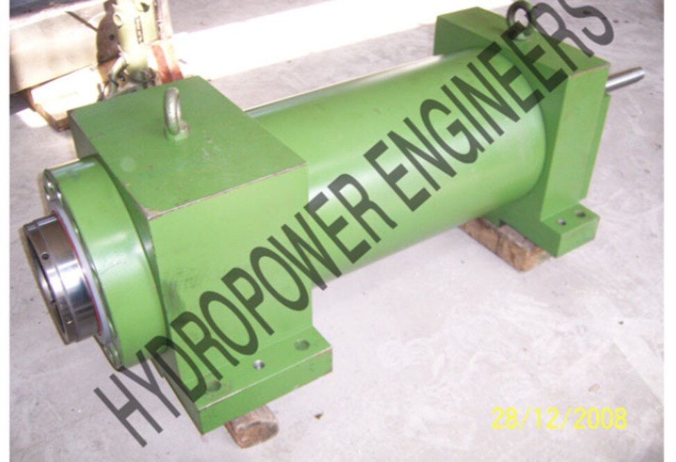
A TMT line can use a servo cylinder for bar positioning, crop-shear movement, straightener adjustment, rolling-line control, or material handling, but the right unit depends on its complete force-speed-stroke duty cycle. By the end, you will be able to identify the controlled motion, size the bore and rod, compare actuator types, and specify the hydraulic, feedback, environmental, and safety details that determine whether the axis will perform reliably.
Key takeaways
- Use servo control for repeatable position, force profiles, or rapid reversals.
- Calculate bore and rod size from peak load, buckling, and guidance forces.
- Match stroke, speed, flow, and heat limits to the complete production cycle.
- Specify feedback, seals, materials, and guarding for the mill environment.
Identify the TMT motion before choosing the cylinder
Bar positioning, crop-shear movement, straightener adjustment, rolling-line gap control, and synchronized handling axes justify a servo cylinder when they demand repeatable position or force profiles, rapid reversals, or controlled deceleration. A slow two-position clamp does not: a conventional cylinder with a directional valve, end sensors, and cushioning is cheaper and easier to maintain.
A servo cylinder for TMT bar machinery is a complete closed-loop axis, not a standard cylinder connected to a larger pump.
| Option | What changes | When it applies |
|---|---|---|
| Conventional hydraulic cylinder | On/off motion using a directional valve and end sensors | Clamping, ejecting, or infrequent two-position travel |
| Proportional hydraulic actuator | Metered valve control, with feedback only if the system includes it | Moderate speed or position control without demanding dynamic accuracy |
| Servo cylinder | Cylinder, position transducer, servo valve, power unit, controller, and load operate as one feedback system | Profiles, synchronization, fast reversals, and controlled force |
| Electromechanical actuator | Motor and screw convert rotation to linear motion | Clean, precise axes with manageable force, shock, and duty cycle |
| Servo motor with ball screw | High positioning accuracy, but exposed screw and nut carry the load | Protected axes without severe mill shock or contamination |
Check the real tooling motion, not the machine’s nominal tonnage. Mill shocks, pinch-roll transients, crop-shear loads, straightener reactions, sudden bar entry, and hard deceleration can create peak force and pressure spikes that average-load calculations miss.
A cylinder-mounted magnetostrictive or LVDT sensor measures piston position, not automatically the bar-contact point. Frame deflection, linkage clearance, rod bending, friction, valve hysteresis, and oil-temperature changes can require external load-side feedback or a validated error model. These are the practical servo cylinder benefits worth paying for.
Size force, bore, rod, and guidance from the real load
Start with the force at the rod attachment, not the machine’s nominal tonnage. Calculate the peak forming or shearing resistance, friction, moving mass × acceleration, and any pressure or mechanical losses.
- Forming force from the bar and tooling
- Friction in guides, rolls, and linkages
- Inertial force during acceleration and deceleration
- Shock from bar entry, crop-shear impact, or a mechanical stop
Add these loads by direction, then apply a documented safety factor that reflects shock severity and uncertainty. Check peak force and average production force separately; a cylinder that survives the peak can still overheat or lose accuracy under continuous duty.
For a differential hydraulic cylinder, use the available pressure at the cylinder after valve and pipe losses. Required piston area is A = F/(p × efficiency), and bore diameter is D = √(4A/π). Extension uses piston area; retraction uses piston area minus rod area, so the two forces and speeds differ at the same flow.
Select rod diameter from a column-stability calculation for the unsupported length, end-fixing condition, material stiffness, and compression load. Do not substitute a catalogue thrust rating for buckling analysis.
Servo actuator selection must also calculate rod-eye side load and bending moment. Use a spherical rod eye, articulated clevis, or externally guided carriage; rod seals and bearings deteriorate quickly under misalignment. A hydraulic servo cylinder needs sufficient structural stiffness and low trapped oil volume, not merely a larger bore.
Match stroke, speed, flow, and heat to the production cycle
A cylinder that reaches the target position in 0.3 seconds can still miss the bar if its acceleration, deceleration, or return stroke is wrong. Define usable stroke plus deceleration distance, mechanical end clearance, and any position reserved for load changes; do not equate nominal stroke with commanded travel.
For servo actuator selection, convert the production cycle into a motion profile:
- Record dwell, extension, acceleration, constant-speed travel, deceleration, retraction, and the time available for each phase.
- Calculate peak velocity and acceleration separately from average cycle speed. Crop-shear impact, pinch-roll entry, and straightener reactions create transient loads.
- Check stopping distance at the highest velocity. Pressure spikes from abrupt deceleration or a mechanical stop can exceed the working-pressure calculation.
Flow follows speed and effective piston area. During extension, Q equals piston area multiplied by velocity; during retraction, Q equals annular area multiplied by velocity, so the same pump flow produces a different speed in each direction.
The servo valve must pass peak flow without excessive pressure drop, while the pump must sustain that flow through the required portion of the cycle.
Cycle time determines average flow and heat, but valve capacity is governed by peak demand. Throttling, leakage, valve pressure drop, and repeated acceleration turn hydraulic power into heat. Size cooling from average losses across the complete cycle, then verify oil, seals, electronics, and nearby mill components at the highest temperature.
Rising oil temperature changes viscosity, leakage, friction, and control tuning—critical for a TMT bar machinery actuator.
Specify feedback, accuracy, construction, and mill-environment protection
Specify position accuracy and repeatability at the tool, not sensor resolution alone. Include commanded stroke, maximum velocity, acceleration, reversal frequency, pressure, leakage limit, and allowable settling time. Frame deflection, rod bending, backlash, oil-temperature changes, valve hysteresis, and seal friction can overwhelm a fine-resolution transducer.
| Feedback choice | Strength | Check before selection |
|---|---|---|
| Magnetostrictive | Integral, non-contact position measurement | Stroke, resolution, repeatability, IP rating, and rod temperature |
| LVDT | Robust analogue feedback for closed-loop control | Mounting concentricity, signal conditioning, vibration, and calibration |
| External linear encoder | Measures motion at the machine member | Exposure to scale and water, alignment, protection, and cable routing |
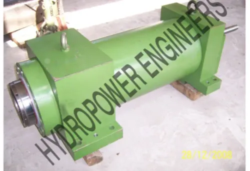
Choose a hydraulic servo cylinder with guided load support or a spherical bearing arrangement when side load or eccentric force exists; do not make the rod bearing carry bending from the tooling. Specify hardened rod material and finish, replaceable guide bushings, low-friction seals, high-temperature compatibility, a heavy-duty wiper, rod scraper, and drainage path.
Water trapped behind a wiper corrodes the rod and carries abrasive scale into the pressure seal.
The servo cylinder benefits disappear when contamination shifts the valve null or makes the spool stick. Define ISO 4406 cleanliness targets, pressure- and return-line filtration, reservoir flushing, fluid compatibility, sampling points, and a commissioning flush; a return filter alone is not enough.
Protect the axis with heat shields, splash guards, sealed connectors, and routed hoses, then verify cooler capacity from average cycle losses and separate checks for seal, sensor, and ambient mill temperatures.
Turn the calculation into a complete and safe actuator specification
Give the manufacturer one controlled-axis data sheet, not a bore-and-stroke request. State the TMT operation, tooling position, bar size range, load direction, cycle sequence, production rate, available pressure, and the required force, stroke, velocity, acceleration, stopping accuracy, repeatability, and duty cycle.
- Cylinder: bore, rod diameter, stroke, mounting, rod-end articulation, allowable side load and moment, working and peak pressure, end cushioning, seal material, guide arrangement, cleanliness class, and mill-temperature exposure.
- Feedback: piston-position transducer type, measuring length, resolution, accuracy, repeatability, mounting, environmental rating, and whether an external tooling-position sensor is needed to compensate for frame deflection, linkage clearance, or compliance.
- Valve and control: servo or proportional valve flow rating, pressure drop, response, hysteresis, manifold layout, controller cycle time, command limits, and tuning data.
- Power unit: pump displacement, maximum flow, accumulator volume, filtration, reservoir capacity, relief setting, cooler duty based on average cycle losses, and allowable oil-temperature range.
- Mechanics: guide or carriage design, rod-eye articulation, hard stops, attachment stiffness, backlash, and the calculated side-load and buckling cases.
- Safety: emergency-stop response, pressure relief, pilot-operated checks or counterbalance valves, overspeed protection, guarded travel, position limits, restart inhibit, and the safe state after hose or sensor failure.
Describe peak crop-shear, pinch-roll, straightener, deceleration, and end-stop loads separately from averages. Hydropower Engineers can then review the complete TMT bar machinery actuator as one dynamic system rather than matching isolated components.
Related product
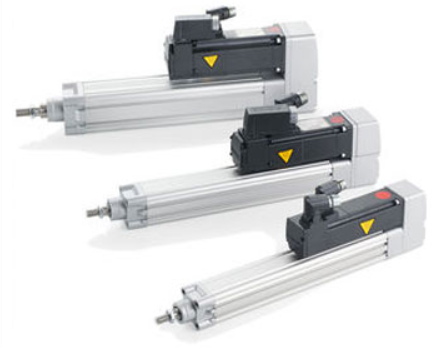 | Hydraulic Cylinders Depending on the requirements in terms of accuracy, servo cylinders are used with two construction designs, which differ in terms of the bearing of... View product → |
Frequently asked questions
When does TMT machinery need a servo cylinder?
Use one for bar positioning, crop-shear movement, gap control, or synchronized axes requiring repeatable position or force profiles, rapid reversals, or controlled deceleration. Use a conventional cylinder for simple two-position motion.
How do you size a servo cylinder for TMT equipment?
Calculate peak and continuous loads, then select bore from required force and pressure. Check rod diameter for compression buckling, side loads, and the guidance arrangement rather than sizing from force alone.
What cycle details must you match before selecting a hydraulic servo cylinder?
Match the cylinder's stroke, extension and retraction speeds, oil flow, acceleration, deceleration, dwell time, reversal frequency, and allowable temperature to the real production cycle.
What should a TMT bar machinery actuator specification include?
State force, pressure, bore, rod, stroke, speed, mounting, guidance, feedback resolution, accuracy, oil and seal compatibility, temperature limits, environmental protection, guarding, and commissioning requirements.