A tube-drawing component can pass a static pressure check and still fail in service through internal bypass, pressure spikes, valve response problems, seal wear, or inadequate flow. You will be able to define the rig’s test scope, size its hydraulic and safety circuits, select measurable specifications, and create component-specific acceptance records.
Key takeaways
- Match every test to the component failure it must expose.
- Set pressure, flow, temperature, and cycle limits before testing.
- Use clean oil and verify every connection before applying pressure.
- Turn measured test conditions into a clear procurement specification.
What a Tube-Drawing Component Test Rig Must Test
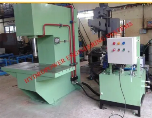
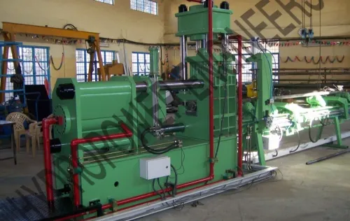
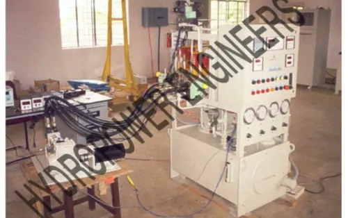
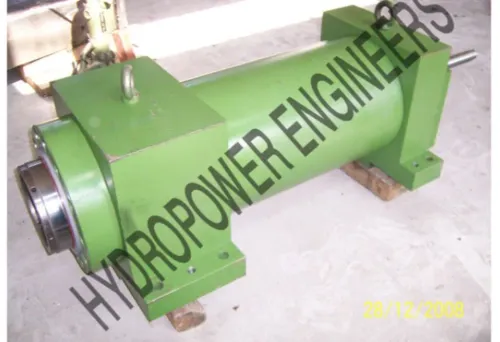
A hydraulic test rig for tube drawing machine components is a controlled system for testing draw cylinders, clamp cylinders, die-box actuators, hydraulic motors, pumps, valves, manifolds, hoses, fittings, and complete hydraulic assemblies. Tube drawing machine testing must match each test to the failure it is meant to expose.
Proof, leak, endurance, function, and performance tests answer different questions:
- A pressure proof test confirms that a pressure-containing cylinder, valve body, manifold, hose, fitting, or connection survives a specified pressure without permanent deformation or leakage.
- A burst test drives the article to rupture pressure and is a destructive design or qualification test, not a routine production check.
- A leakage test measures external leakage, internal bypass, pressure decay, or cylinder drift. “No visible leak” will not reveal a piston seal that cannot hold load.
- An endurance cycle test applies repeated pressure or motion. Record the pressure range, cycle count, ramp rate or frequency, oil temperature, detection method, and acceptance limits.
- A functional test checks cylinder and valve movement, response time, stroke, repeatability, and holding performance under controlled flow and load.
- A performance test measures loaded motor or pump speed, torque, flow, pressure, efficiency, and temperature rise.
ISO 10771-1 covers fatigue pressure testing of metallic pressure-containing envelopes, including cylinders, valve bodies, and manifolds. Hydraulic component test equipment is incomplete if “endurance tested” lacks those parameters and post-cycle acceptance results.
The Safe, Repeatable Test Sequence
The lowest-rated item sets the allowable working pressure: the test article, hose, adapter, manifold, gauge, valve, or pressure transducer. Do not rate the circuit from the pump nameplate.
1. Inspect the component, ports, seals, fittings, hose condition, adapter ratings, and blanking surfaces. Reject damaged threads, cracked fittings, and mismatched connection standards.
2. Flush the hydraulic test rig for tube drawing machine components and the test article with filtered fluid. Confirm the specified cleanliness level before connection.
3. Install rated blanking plates or approved adapters, then tighten each connection using its documented torque or installation method.
4. Fill the circuit slowly and bleed every high point. Trapped air stores energy and can cause pressure spikes, erratic actuator movement, or a false leak result.
5. Verify the primary relief valve and an independent over-pressure protection method before pressurising. Check the emergency dump or unload valve.
6. Ramp pressure at a recorded, defined rate. Hold the specified proof pressure for the specified time, then record pressure decay.
7. Cycle the component through its required stroke, speed, load, or switching sequence. Tube drawing machine testing must capture response time, repeatability, internal bypass, and drift, not only visible leakage.
8. Inspect externally during and after the hold and cycle. Stop for hose bulging, fitting movement, spray, seal damage, or abnormal temperature.
9. Verify relief-valve operation at the documented setting, then isolate stored energy and depressurise through the controlled dump or unload path.
Use an enclosure, remote operation, interlocked doors, emergency stop, stored-energy isolation, hose-failure protection, and a controlled depressurisation path under ISO 4413. Never loosen a fitting to release pressure.
Specifications and Circuit Sizing That Match the Component
A 160-bar test article does not need a 350-bar pump. Choose the lowest pressure band that reaches the required test point: 100–160 bar, 250–350 bar, or a higher band only when the component design demands it. Oversizing adds stored energy, cost, leakage risk, and safety burden without improving the test.
| Pressure band | Suitable use | Main caution |
|---|---|---|
| 100–160 bar | Lower-pressure controls and actuators | Do not exceed the lowest-rated circuit item |
| 250–350 bar | Many industrial hydraulic circuits | Verify hose, valve, adapter, and transducer ratings |
| Above 350 bar | Components specifically designed for higher pressure | Add engineered guarding and over-pressure protection |
Specify these values in the hydraulic test rig specifications in Chennai or any supplier RFQ: maximum test pressure, continuous operating pressure, flow range, pressure-control accuracy, flow-control accuracy, reservoir capacity, motor rating, filtration rating, oil-temperature control range, transducer range, data-acquisition rate, independently controlled circuit count, test-fluid viscosity range, and largest component envelope.
Record fluid temperature during acceptance testing.
- Start with the component’s required pressure and peak flow.
- Add pressure losses through hoses, filters, valves, and fittings.
- Select hydraulic component test equipment that reaches the target without exceeding the test article rating.
- Size the relief valve and unload circuit for the pump’s maximum possible delivery, with independent over-pressure protection.
- Measure pressure and flow at the device under test. Pump nameplate flow ignores restriction, viscosity, temperature, and filter loading.
Connections, Cleanliness, and Component Measurements
Use SAE or DIN ports with adapters rated above the rig’s maximum pressure, and blank unused ports with rated plugs or plates. Select hoses for working pressure, proof pressure, burst rating, impulse rating, bend radius, and installation method; a hose that reaches pressure once can still fail under cycling.
Apply ISO 19879 test methods to metallic tube connections, including pressure-tightness, proof, burst or impulse testing where applicable, and assembly-torque records.
- Flush the rig, hoses, adapters, and component before connection.
- Take a fluid sample at the device-under-test return or test-point port, upstream of the filter, using a flushed sampling bottle and avoiding dead legs.
- Define an ISO 4406 target, such as 16/14/11, and record whether the sample represents clean oil, operating oil, or a loaded filter.
- Inspect filter elements and record differential pressure; replace a damaged or bypassing element before tube drawing machine testing.
- Request ISO 11171 calibration traceability for the automatic particle counter, plus the sampling date and procedure.
- Bleed trapped air, verify every connection, and check pressure and flow at the component rather than relying on pump ratings.
Record cylinder rod position, stroke speed, cycle time, repeatability, drift under load, internal bypass, rod-seal leakage, pressure decay, and force from effective piston area, rod-side pressure, mechanical losses, and transients.
Hydraulic component test equipment for motors must record speed, torque, direction, case-drain flow, inlet and outlet pressure, temperature rise, volumetric efficiency, and mechanical efficiency under load.
Record oil temperature throughout testing. Viscosity changes affect leakage, valve flow, pressure drop, and seal behaviour. Define acceptance limits at cold start, stabilized temperature, or a stated temperature band.
Turning the Test Envelope into a Procurement Specification
Specify the rig as a measurable test envelope, not as a “high-pressure” package. Put these questions into the RFQ:
1. What are the maximum, continuous and peak pressures, flow range, test-fluid viscosity, circuit count, reservoir volume, motor rating and largest component envelope? State whether the design is 160 bar, 350 bar or another justified class; an oversized pump adds stored energy and leakage risk.
2. What filtration grade and ISO 4406 cleanliness target will the supplier guarantee? Request the sampling point, sampling method, filter condition and ISO 11171 calibration traceability for the automatic particle counter.
3. Give oil-temperature control and acceptance bands, transducer and flow-meter ranges, pressure and flow accuracy, logging rate, calibration certificates, connection standards such as SAE or DIN, and the motor’s continuous and peak ratings.
4. Show guarding, interlocked doors, emergency stop, stored-energy isolation, hose-failure protection, independent over-pressure protection and controlled depressurisation through a dump or unload valve.
5. Define separate acceptance limits for external leakage, internal leakage or drift, pressure decay over a stated time, relief-valve setting, response time, repeatability and post-cycle performance. “No visible leak” will not reveal internal bypass.
Ask Hydropower Engineers to document the test envelope, independently rated circuits, instruments, safety functions and a sample test report before quotation. An industrial test rig supplier that supplies only a pressure hold is not supplying complete production validation. Include component type, cycle count, ramp rate, oil temperature and post-cycle checks in the acceptance schedule.
Related product
 | Hydraulic Testrig Hydropower Engineering Systems offers advanced Hydraulic Test Equipment designed for precise testing and evaluation of automobile components and... View product → |
Frequently asked questions
What components can a hydraulic test rig test?
It can test draw cylinders, clamp cylinders, die-box actuators, hydraulic motors, pumps, valves, manifolds, hoses, fittings, and complete hydraulic assemblies.
What should a tube-drawing component test sequence include?
The sequence should define the connection checks, controlled pressure and flow application, operating cycles, measurements, and safe shutdown steps.
Which specifications must match the component under test?
Size the rig around the component’s required pressure, flow, temperature, cycle rate, connection type, and measurement range.
Why do cleanliness and connections matter during hydraulic testing?
Contamination and incorrect connections can damage components, distort measurements, and create unsafe pressure-release conditions.