Choosing this equipment requires more than matching a quoted tonnage to a product drawing. You will be able to define the LFI process, calculate the forming load, specify fin calibration and inspection, and test whether a Chennai installation is genuinely ready for production.
Key takeaways
- Match press force and stroke to mould area, part depth, and opening clearance.
- Record fin height, thickness, pitch, and profile against drawing tolerances.
- Check power, floor loading, ventilation, resin handling, and fibre-cutting space.
- Compare suppliers on commissioning, controls, tooling support, and measurement records.
What LFI moulding produces and how it differs from other processes
Long-fibre injection (LFI) moulding produces lightweight glass-fibre-reinforced polyurethane panels, covers, housings, structural shells and other large contoured parts. A mixing head combines resin with chopped glass fibre and places the charge in or onto the mould, creating a composite part rather than a solid plastic casting.
LFI is not a universally controlled name for one press architecture. Before comparing quotations, ask the supplier to define the resin system, tube or insert material, fibre length, fibre loading, mould arrangement and fin geometry represented by “LFI moulding press.”
| Process | What it makes and how material enters | Main difference from LFI |
|---|---|---|
| LFI moulding | Large reinforced polyurethane parts using chopped long glass fibre | Fibre and resin are placed together as a wet charge; fibre orientation and surface finish depend on deposition and mould control |
| Compression moulding | Composite parts from a measured charge compressed between heated mould halves | The charge is formed mainly by closing force; it does not rely on LFI’s fibre-resin deposition method |
| RTM | Reinforced closed-mould parts from dry fibre preforms and injected resin | Resin fills a sealed mould around reinforcement, giving controlled fibre placement but requiring preform and vent management |
| SMC | Panels and covers from sheet moulding compound containing resin, fillers and chopped fibre | A prepared sheet is cut and compressed, rather than mixed and deposited at the press |
| Plastic injection moulding | Thermoplastic parts from pellets injected into a closed mould | It normally uses short-fibre or unfilled melt, not a wet long-fibre composite charge |
For hydraulic LFI moulding press fin calibration in Chennai, specify tube outside diameter, wall thickness, fin height, pitch, thickness, calibrated length, straightness and allowable variation. “Precision fin calibration” alone is not an acceptance criterion.
The production cycle from mould loading to part removal
An LFI cycle controls finished-part quality through five linked stages: mould preparation, loading, controlled closure, charge injection or placement, and cure before removal. Clean the cavity, apply the specified release agent, position the tube and inserts, then use mandrels, guide bushes or internal supports where a thin wall could buckle or ovalise.
| Stage | What happens | Quality control |
|---|---|---|
| Mould loading | Place the tube, inserts and charge in the defined locations. | Check orientation, support contact and clearance from the die. |
| Closing and tilting | Close the industrial moulding press in Chennai at the programmed speed and tilt the mould if the process requires it. | Confirm alignment; excessive speed can shift the tube or trap air. |
| Injection or charge placement | Deliver the resin-and-long-fibre charge, or place the prepared charge, according to the approved process definition. | Record material batch, shot weight, injection pressure and fill time. |
| Pressure hold and cure | Maintain pressure while the material consolidates and cures at the specified temperature and time. | A pressure drop, cold spot or early release can leave voids, distortion or weak bonding. |
| Opening and removal | Retract the platen, open the mould and remove the part without levering against fins or thin walls. | Inspect flash, incomplete fill, surface damage and spring-back immediately. |
Keep the load-versus-stroke or pressure-versus-time record for each approved cycle. Measure tube outside diameter, fin height, pitch, thickness, calibrated length and straightness after trimming or calibration; a sound cycle record does not prove dimensions that were never measured.
How to size the press from force, stroke and control requirements
Calculate required mould force in newtons: projected area in mm² × cavity pressure in N/mm² × number of cavities. Add the forming and fin-calibration load, then apply a documented safety margin.
The result must remain below the press’s usable force across the stroke; a nominal 500-ton rating is meaningless if the frame deflects or the hydraulic circuit cannot hold pressure at the working position.
| Quotation item | Specify | Why it matters |
|---|---|---|
| Press capacity | Usable force, force-versus-stroke curve and maximum working pressure | Prevents overload near full stroke |
| Tool fit | Platen length and width, daylight opening, stroke and shut-height range | Confirms the mould can close and eject safely |
| Motion | Closing speed, forming speed, return speed and controlled low-speed approach | Controls material flow and fin dimensions |
| Hydraulics | Pump flow, motor power, pressure-compensated control, proportional valves and return filtration | Protects repeatability and oil cleanliness |
| Control | Pressure-hold time, end-of-stroke sensing, recipe storage and alarm history | Makes each cycle traceable |
| Acceptance | Load-versus-stroke or pressure-versus-time record, die drawings and inspection results | Proves the quoted performance |
State tube outside diameter, wall thickness, fin height, pitch, thickness, calibrated length, straightness and allowed variation. Ask the supplier to calculate the load from those values, not from tonnage alone.
Treat LFI moulding press availability as separate dates for ex-stock frame, completed hydraulics, application dies, factory acceptance testing, installation and commissioning. A physically available press can still lack the controls or gauges needed for production.
Fin calibration: dimensions, tooling choices and measurement records
Fin calibration corrects fin height, pitch, profile and local springback after forming; it is a sizing operation, not cosmetic polishing. It cannot recover metal lost through tearing or excessive fin thinning, and it cannot close a cracked fin root. Specify the correction from the actual alloy, temper, fin height-to-thickness ratio, bend radius and forming direction.
| Fin calibration equipment | What it corrects | When it applies |
|---|---|---|
| Hydraulic press with matched calibration die | Height, pitch and profile along a defined length | Controlled over-forming of individual tubes |
| Rotary or roll-sizing tooling | Progressive pitch and profile variation | Long, continuous finned sections |
| Mandrel-supported die and guide bushes | Ovalisation, local buckling and unsupported-span distortion | Thin-wall tubes or long calibration lengths |
A calibration die copied directly from the nominal finished profile often produces undersized fins because springback changes the released shape. Use a documented over-form or correction allowance, then prove it on the buyer’s actual tube alloy and dimensions.
Put these acceptance values on the drawing or purchase specification:
- Tube outside diameter and wall thickness
- Fin height, pitch, thickness and profile
- Calibrated length and straightness
- Permitted variation for every dimension
Measure several positions along each tube, not one visually acceptable sample. Use a calibrated height gauge or vision system for fin height and pitch, a micrometer for fin thickness, and a CMM or profile projector for profile and root geometry. Record instrument ID, calibration due date, tube batch, position measured, result, operator and press temperature.
Repeat the measurements across consecutive parts after the hydraulic circuit reaches operating temperature; proportional control, stable pressure, clean return filtration and repeatable end-of-stroke sensing determine whether fin calibration remains consistent.
How Chennai buyers should evaluate suppliers and site readiness
A quotation is not proof that a press is ready to ship. Because “LFI” does not define one standard press architecture, ask the supplier to state the process, tube alloy, outside diameter, wall thickness and fin geometry used in its demonstration. Compare process capability, not tonnage alone.
1. Verify the supplier with a trial using your actual tube dimensions. Require fin height, pitch, thickness, calibrated length, straightness and allowable variation, measured at several positions after the hydraulic system reaches operating temperature. Ask for repeatability results, not one acceptable sample.
Hydropower Engineers, for example, should be assessed by this evidence rather than by a catalogue description.
2. Split LFI moulding press availability into ex-stock status, frame completion, hydraulic-system completion, tooling readiness, factory acceptance testing and installation commissioning. Confirm which date applies to each item; a completed frame does not prove that dies, controls or gauges are ready.
3. Make acceptance documentation part of the purchase order. Request load-versus-stroke or pressure-versus-time records, representative-tube inspection results, die drawings, hydraulic and electrical schematics, oil specification, and critical seal, filter and valve lists.
4. Survey the Chennai site before delivery. Record incoming voltage and phase capacity, protective earthing, panel enclosure rating, foundation or floor loading, unloading route, maintenance clearance, lifting equipment, hydraulic-oil storage and spill containment.
5. Reject delivery plans that omit guarding, interlocked access doors, emergency stops, pressure relief, lockout points and operator training. Require installation drawings and a commissioning checklist before the truck is booked.
Related product
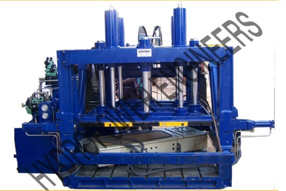 | Hydraulic Moulding Press Hydropower hydraulic LFI moulding presses are engineered for reliability, durability, and high performance in demanding applications. View product → |
Frequently asked questions
What does LFI moulding produce?
LFI moulding produces large, lightweight glass-fibre-reinforced polyurethane panels, covers, housings, structural shells, and contoured parts.
How do you size a hydraulic LFI moulding press?
Size it from required closing force, mould opening area, stroke, daylight, platen dimensions, and control requirements.
What should fin calibration records include?
Record fin height, thickness, pitch, profile, measurement points, instruments used, readings, tolerances, and operator or inspection details.
What should Chennai buyers check before installing an LFI press?
Check floor capacity, electrical supply, ventilation, resin and fibre handling areas, access for delivery, operator safety, and commissioning support.