A hydraulic system is worth paying for only when its force, speed, duty cycle and service demands fit the tube, tooling and production schedule. By the end, you will be able to compare hydraulic, servo, mechanical, pneumatic and manual drives, estimate the pack size, and calculate whether the operating cost justifies the capacity.
Key takeaways
- Match cylinder force and speed to the bend, not motor size alone.
- Choose hydraulic drive for high-force, repeatable work across multiple stations.
- Calculate pressure, flow, torque and duty cycle before selecting a power pack.
- Test heat, noise, leakage, controls and service access before a Chennai installation.
What the Hydraulic System Actually Powers
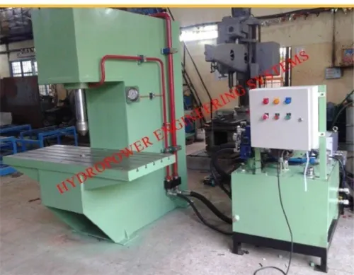
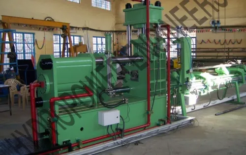
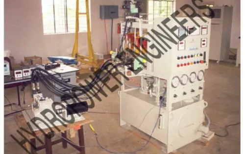
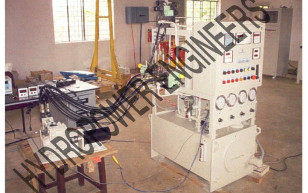
Hydraulic power earns its place when a tube-bending machine must apply high force briefly, repeatably, and across more than one station. A hydraulic power pack tube bending system combines an electric motor, pump, reservoir, filter, relief valve, directional valves, hoses and actuators; the ratings must match both force and motion, not motor size alone.
Pressure × flow ÷ 600 gives hydraulic output in kilowatts: 160 bar at 40 L/min produces about 10.7 kW before losses.
The movements that most often justify tube bending machine hydraulic power are:
- Clamp closing and locking: specify clamping force in kN, cylinder bore, stroke and closing time.
- Pressure-die loading: specify thrust in kN and stroke; insufficient force allows the tube to flatten or buckle.
- Mandrel insertion and extraction: specify cylinder force, stroke and retract speed.
- Carriage pushing or booster movement: specify thrust, travel speed and duty cycle.
- Bending-die rotation: specify actuator torque in Nm, angular speed and bend angle; a servo or mechanical drive may suit this axis better.
| Movement | Hydraulic rating | What to compare |
|---|---|---|
| Clamp or pressure die | Force in kN, stroke in mm | Servo or mechanical clamp repeatability |
| Mandrel or carriage | Force in kN, flow in L/min | Required travel speed and cycle time |
| Rotary bending axis | Torque in Nm, speed in rpm | Servo positioning and mechanical gearing |
| Complete circuit | Pressure in bar, flow in L/min, motor kW | Idle losses, heat rejection and maintenance |
Actual actuator pressure falls below the relief-valve setting because valves, hoses and fittings create pressure drop. Size the electric motor above calculated hydraulic output, and check cooler capacity against worst-case duty cycle and ambient temperature.
When Hydraulic Drive Beats Servo, Mechanical or Manual Bending
Hydraulic drive earns its cost when one power pack feeds several force-intensive stations, or when each cycle demands force that a servo or mechanical drive would need oversized hardware to deliver.
Tube bending rewards it for intermittent clamping, pressure-die loading, mandrel extraction, carriage pushing and booster work—not for one small tube moving through a modest-force axis.
A hydraulic power pack value in industrial use calculation must include idle time. A fixed-displacement pump that sends excess flow across the relief valve turns unused motor power into heat; unloading, pressure compensation or load sensing improves the case.
At 160 bar and 40 L/min, the circuit supplies about 10.7 kW of hydraulic power before losses.
| Option | Cost and production effect | Choose it when |
|---|---|---|
| Hydraulic | High force density; one pack can serve several axes | Clamping, mandrel, booster and carriage loads recur across production |
| Servo-electric | Efficient during dwell; precise low-speed positioning | One axis handles modest force and repeatable motion |
| Mechanical | Strong output with few hydraulic components | A fixed stroke and high-volume cycle justify dedicated tooling |
| Manual | Lowest equipment cost; slowest output | Short runs, prototypes or occasional repairs |
Choose hydraulic power when:
- Several stations operate from the same pack, spreading pump, reservoir and controls across the machine.
- Large tubes, thick walls, difficult alloys or short cycle times create high intermittent force.
- The machine runs enough hours to recover energy and maintenance costs.
Choose a servo or hybrid design when long idle periods, clean-room restrictions, leak sensitivity or fine low-speed positioning dominate. A hydraulic power pack for tube bending machine in Chennai also needs site-specific cooler, ventilation and electrical checks; location alone is not a specification.
How to Estimate Force, Torque and Power Before Choosing a Pack
Start with the worst operation, not the motor size. Record the tube’s outside diameter, wall thickness, material grade, bend angle, centre-line radius, number of bends per part, batch size and target cycle time. Add clamp, pressure-die, mandrel, carriage and booster loads if they operate during the same cycle.
Collect these machine inputs before requesting a pack:
- Required actuator stroke and speed for every cylinder
- Peak bending torque at the die, plus tooling and linkage efficiency
- Maximum force for clamping, pressure-die loading and mandrel extraction
- Number of axes moving simultaneously
- Peak cycles per minute and dwell time between cycles
- Available electrical supply, ambient temperature and contamination exposure
| Quantity | Data needed | Calculation consequence |
|---|---|---|
| Pressure | Required process force, cylinder bore and rod diameter | Force equals effective pressure multiplied by piston area |
| Flow | Cylinder displacement, stroke, speed and simultaneous axes | Flow determines actuator speed |
| Torque | Tube geometry, material strength, bend radius and die leverage | Torque converts into cylinder force through tooling geometry |
| Motor size | Peak pressure, total flow, duty cycle and system losses | Hydraulic power is pressure × flow ÷ 600 in kW |
For example, 160 bar at 40 L/min provides about 10.7 kW before pump, valve, hose and motor losses. Select the electric motor above that figure, then check starting and continuous duty. A fixed pump that unloads excess flow across the relief valve turns idle capacity into heat.
Do not set relief pressure at the pump’s maximum rating. Set it from the required process force and the weakest rated hose, valve, manifold or cylinder, because pressure drops and tooling friction reduce force at the tube. That calculation tells you whether tube bending machine hydraulic power is justified.
The Sizing Details That Decide Reliability and Running Cost
A pump sized only for peak cylinder speed wastes energy during every clamp, dwell and return stroke. Calculate required flow at the slowest acceptable cycle, then check motor power at working pressure; specify variable-displacement, pressure-compensated control or pump unloading when a fixed pump would dump excess flow across the relief valve.
- Reservoir: start with about 3–5 times rated pump flow in litres per minute, then increase volume for cooling, air release and contamination margin. Confirm the oil level never uncovers the suction port during cylinder movement.
- Directional valves and manifold: rate them for maximum flow and pressure, and measure pressure drop at that flow. A valve that is adequate on paper can slow the bend and create heat.
- Hoses and return circuit: size bore for the manufacturer’s velocity limit, not the port size. Check return pressure through hoses, manifolds, coolers and filters; back-pressure reduces speed and raises temperature.
- Filters: select suction protection, pressure filtration and return filtration by flow, dirt capacity, beta rating and bypass setting. A blocked return filter must trigger a warning before bypass opens.
- Cooler: calculate heat rejection from pump losses, throttling and leakage at worst-case duty and maximum ambient. Four kilowatts lost requires roughly four kilowatts of heat removal, not a cooler chosen from motor kilowatts.
- Safety hardware: set the relief valve below the weakest rated component, and add pressure indication, emergency unloading, guards and counterbalance or overcentre valves where gravity or stored force exists.
- Accumulator: use one for brief flow peaks only; include recharge time, precharge checks, isolation and automatic discharge protection.
For hydraulic power systems in Chennai, include ambient temperature, electrical supply, ventilation, dust and service access in the specification. Those conditions determine cooler capacity and oil-change intervals.
A Practical Purchase Test for a Chennai Installation
Do not approve a hydraulic purchase until the supplier proves the pack against your part, duty cycle and Chennai site conditions. Ask for a written acceptance sheet, not a motor-kilowatt figure.
1. Ask which movements use hydraulics: clamp, pressure die, mandrel, carriage, bending die or booster. Require force, stroke, speed and cycle-time figures for each axis.
2. Give the supplier your maximum pressure and flow requirement, then check the calculation: pressure × flow ÷ 600. At 160 bar and 40 L/min, hydraulic output is 10.7 kW before losses, so the motor must exceed that figure.
3. Request pressure readings at the actuator while bending, not only the pump outlet setting. Hose, valve and manifold losses reduce available force; the relief setting must protect the weakest rated component.
4. Ask for cooler capacity at your worst ambient temperature and duty cycle. If 4 kW becomes heat through throttling, leakage and inefficiency, the system must reject roughly 4 kW.
5. Confirm what happens during dwell periods. A fixed-displacement pump unloading across relief wastes energy; pressure-compensated, variable-displacement or load-sensing control can reduce idle heat.
6. Verify the electrical supply, enclosure ventilation, oil grade, filtration, contamination controls, service clearances and replacement-filter access. Hydraulic power systems in Chennai need site-specific cooling and maintenance provisions.
Whether you consult Hydropower Engineers or another supplier, demand a measured factory trial using your tube, tooling and complete programmed cycle before committing. A servo axis remains the better investment when force is modest and positioning accuracy dominates.
Frequently asked questions
What does a hydraulic system power on a tube-bending machine?
The power pack supplies pressurised oil to hydraulic cylinders or motors that perform bending, clamping, mandrel movement and other machine actions.
When does hydraulic drive beat servo, mechanical or manual bending?
Hydraulic drive suits high-force, intermittent and multi-station bending. Servo systems suit precise programmable motion and energy control, while mechanical or manual systems fit simpler, lower-force work.
How do you estimate hydraulic power for tube bending?
Start with required actuator force and speed. Cylinder force depends on pressure and piston area, while hydraulic power depends on pressure and flow; include losses and the machine duty cycle.
What should you test before installing a hydraulic power pack in Chennai?
Check the pressure and flow ratings, reservoir and filtration, heat management, noise, leakage, control response, electrical compatibility, service access and spare-parts support.