A foam moulding machine needs enough closing force at every telescopic stage, enough travel to clear the mould, and enough control to stop without impact or drift. By the end, you will be able to calculate the load and stroke, check fit and guidance, compare actuator arrangements, and prepare a specification that a cylinder supplier can quote accurately.
Key takeaways
- Calculate net force from pressure, effective area, losses and safety margin.
- Check closed length, extended length, side loads and external guides before sizing.
- Use stage sequencing and cushioning to control speed and stopping.
- Send load, stroke, pressure, mounting and duty-cycle data for an accurate quotation.
How do you calculate the force and stroke the mould needs?
Calculate required force from the maximum load needed to close, hold, or open the mould, then identify whether the cylinder pushes, pulls, or holds the platen. For extension, theoretical force equals hydraulic pressure multiplied by effective piston area. Subtract seal friction, rod effects, back-pressure and dynamic losses, then apply a defined safety margin.
For retraction, use annular area: piston area minus rod area. Never use extension force for a pull load.
| Load direction | Calculation basis | Design check |
|---|---|---|
| Push | Pressure × effective piston area | Use the smallest effective area among extending stages, not the first-stage bore or outside diameter |
| Pull | Pressure × (piston area − rod area) | Request separate retraction force data |
| Hold | Net force during dwell | Resist foam expansion, mould adhesion and every external separation force |
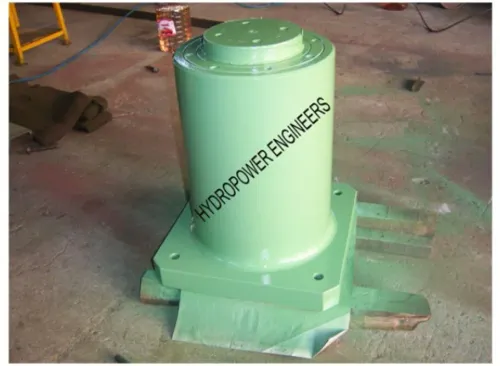
The foam moulding machine cylinder options must include stage-by-stage force and pressure data. Size the cylinder from the weakest extending stage, because later telescopic stages have less area.
Calculate stroke from closed mould height, part geometry, required mould opening, loading and unloading clearance, plus travel for cleaning or tool changes. Compare extended length with the installation envelope, then confirm retracted length fits between the frame, platen and hydraulic connections.
Record load, force at each stroke position, stroke, speed, cycle frequency, dwell time and allowable drift before selecting the cylinder.
How do fit, mounting and external guides determine cylinder size?
Size the cylinder from the layout and guidance system, not from the platen envelope alone. Create a dimensioned drawing showing closed and extended lengths, every stage or bore diameter, rod diameter, port position, and clearance around each moving stage. Mark whether the load is centred on the cylinder axis.
Specify the mounting style and geometry:
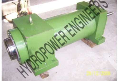
- Identify a clevis, trunnion, flange or cross-tube mount, with pin diameter, pin length, bearing width and available swing angle.
- Show mould offset, maximum eccentricity, load direction and platen travel. Offset mould halves, uneven foam loading, guide-rail friction and platen movement create side thrust.
- Provide machine columns, guide pillars, linear bearings or another external guide to react that thrust. Make guides mandatory if the platen can rack, mould halves are offset, loading is uneven, or the supplier gives no quantified side-load and misalignment limit.
- State allowable misalignment in millimetres or degrees, guide clearance and the limit for lateral movement. Check buckling and bending at maximum extension, where the smallest stage has the lowest lateral stiffness.
Do not let the cylinder align the platen. Side loading accelerates seal wear, scores stages and can buckle the extended assembly. A compact retracted envelope is one of the main telescopic cylinder benefits for industry, but it does not justify sacrificing platen guidance.
Ensure the drawing shows guide clearances through the full stroke and leaves ports, pins and stages accessible for maintenance.
How do telescopic stages affect force, speed and stopping control?
In telescopic hydraulic cylinder applications, extension normally starts with the largest stage and proceeds toward smaller stages. Later stages have less effective area, so force falls at the same pressure while speed rises at the same oil flow. Request stage-by-stage force and pressure data, not one nominal rating.
| Stage position | Effective area | Force at constant pressure | Speed at constant flow |
|---|---|---|---|
| First, large stage | Largest | Highest | Lowest |
| Later, smaller stage | Reduced | Reduced | Higher |
| Final stage | Smallest | Lowest | Highest |
Calculate each stage speed as v = Q ÷ A, using compatible flow and area units. Check every stage, not only the nominal cycle rate. A compact cylinder saves installation space, yet a limited pump flow can leave the overall mould cycle slow even when later-stage speed increases.
Retraction does not follow automatically from extension order. Gravity, an external load or a spring returns a single-acting cylinder; a double-acting design uses pressure and may need internal sequencing or special porting. Choose positive hydraulic retraction when mould adhesion, a light platen, an unbalanced load or non-vertical installation could prevent return.
For rapid closing, specify:
- Adjustable end-of-stroke cushioning for every stage
- Meter-out flow control, proportional valves or an external deceleration circuit
- A correctly set relief function, adequately sized hoses and valves, and protection against overrunning or suspended loads
- A position transducer or external linear measurement when compression height matters
Valve timing alone cannot ensure repeatability because compressibility, leakage, trapped air and temperature changes cause drift.
Which actuator arrangement suits the moulding motion?
Choose a telescopic cylinder when the working stroke is long but the retracted installation length is short. The packaging gain costs extra stages, seals, friction variation and lower lateral stiffness. Accept that trade when a conventional single-stage cylinder will not fit; otherwise, the conventional unit is usually simpler, stiffer and easier to cushion.
| Actuator arrangement | Strength | Main limitation |
|---|---|---|
| Telescopic hydraulic cylinder | Long stroke from a short envelope | More seals, changing friction and lower extended stiffness |
| Two conventional cylinders | Shares platen load and reduces twisting | Needs synchronisation, matched flow paths and a load-sharing frame |
| Hydraulic lift mechanism | Supports a guided vertical platen with mechanical advantage | Adds pivots, structure and maintenance points |
| Pneumatic actuator | Clean, fast, lower-force movement | Poor for high closing force, controlled dwell or mould adhesion |
For a vertical machine, use a single-acting telescopic cylinder only when gravity or a verified external load reliably returns every stage. Choose powered retraction when adhesion, platen hang-up or a non-vertical arrangement could prevent return.
Check these foam moulding machine cylinder options against the actual service:
- Confirm hydraulic-fluid compatibility, operating temperature, contamination, cleaning chemicals, duty cycle and cycle life.
- Specify seal material, wiper design, corrosion protection and stage surface treatment; exposed stages face moisture and contamination during extension.
- Use external guides for platen alignment. Telescopic hydraulic cylinder applications such as lifting platforms do not justify letting the cylinder carry side load.
What should you send a Pune supplier for a reliable quotation?
Send a complete motion profile, not a request for a cylinder by bore and stroke.
State the closing, opening and holding loads; force at each stroke position; push, pull or hold direction; stroke; retracted envelope; extension and retraction speeds; cycle frequency; dwell time; stop accuracy; allowable drift; platen mass; load balance; hydraulic pressure; available pump flow; fluid type; temperature; cleanliness target; and filter location.
Missing these inputs produces a plausible drawing that fails at the machine.
- Request a quotation drawing showing every stage’s retracted and extended dimensions, stage diameters, mounting geometry, pin diameter, ports, cushion details, load direction, allowable misalignment, rated and test pressures, mass, surface treatment and seal materials.
- Request stage-by-stage force, pressure and speed data, the sequencing method, test documentation, spare-seal availability and local repair capability.
| Evidence | Reliable quotation | Warning sign |
|---|---|---|
| Drawing | Complete stage dimensions, ports and mounting data | Bore, stroke and outside diameter only |
| Performance | Stage force, pressure, speed and sequence | One nominal pressure and speed |
| Service | Test records, seal spares and repair support | Heavy duty or high pressure labels |
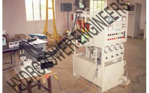
For a telescopic cylinder for foam moulding machine in Pune, Hydropower Engineers can review these constraints alongside the hydraulic circuit and moulding equipment. Compare drawings and service evidence, then confirm commissioning requirements, air bleeding, contamination control, emergency load support and the guide-alignment checking procedure before production.
Related products
 | Hydraulic Cylinders Hydropower Engineering Systems offers high-performance Telescopic Cylinders, also known as multistage hydraulic cylinders, designed for applications... View product → |
 | Hydraulic Moulding Press This equipment is designed for moulding automobile seat cushions for both two-wheelers and four-wheelers. View product → |
Frequently asked questions
How do you calculate the force and stroke the mould needs?
Calculate net force from hydraulic pressure and effective piston area, then subtract friction, rod effects, back-pressure and dynamic losses. Specify the full working stroke and add a defined safety margin.
How do fit, mounting and external guides determine cylinder size?
Compare the cylinder’s retracted and extended lengths with the machine envelope, then confirm pin or flange mounting, alignment and available external guides. Use guides to control side loads rather than transferring them to the cylinder.
How do telescopic stages affect force, speed and stopping control?
Each smaller stage provides less effective area and force at the same pressure. Stage changes also alter speed and stopping behaviour, so use sequencing, cushioning and flow control where the mould needs controlled motion.
Which actuator arrangement suits the moulding motion?
Choose a single-acting, double-acting or paired-cylinder arrangement according to whether the mould only needs powered extension or requires controlled opening and retraction. Match the arrangement to load direction, alignment and holding requirements.
What should you send a Pune supplier for a reliable quotation?
Send the required force, stroke, retracted length, operating pressure, speed, duty cycle, mounting drawing, load direction, guide details, oil specification and environmental conditions.