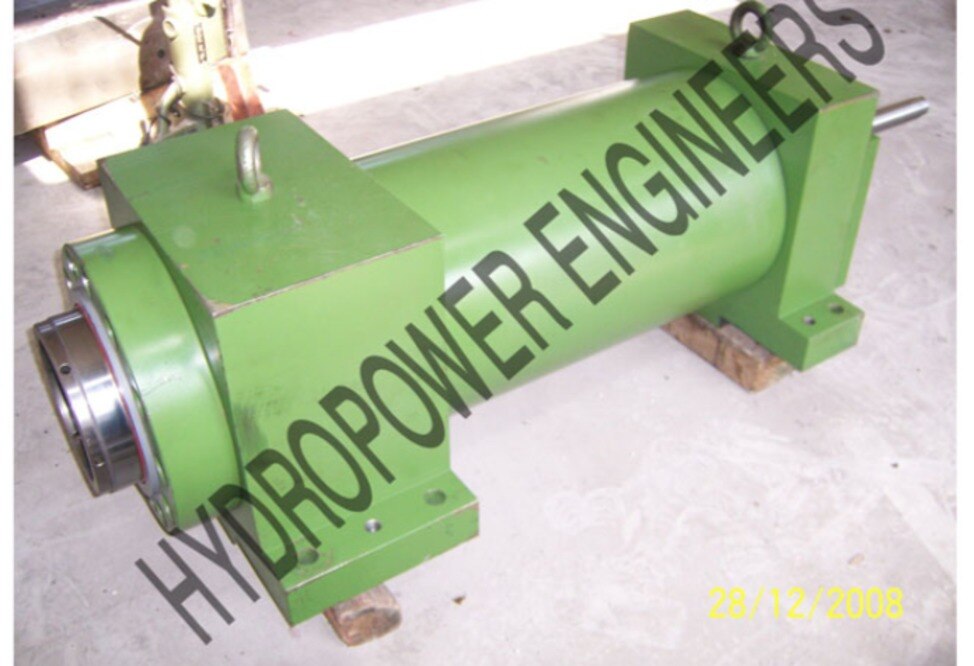
A cylinder’s advertised tonnage does not tell you the force reaching the squeeze-bending tool, whether the rod will buckle, or whether the machine can repeat the shape at production speed. By the end, you will be able to calculate the required bore, compare meaningful specifications, design the mounting interface, and prepare an automotive tube-work specification for supplier review.
Key takeaways
- Calculate force from tube, tooling, friction, and machine mechanical advantage.
- Match push, pull, or opposed cylinders to each bending-machine stage.
- Specify bore, stroke, pressure, guides, mounting, seals, and fatigue duty.
- Validate supplier calculations, testing records, drawings, and automotive tube-work experience.
Calculate the cylinder force from the tube and tool load
Size the cylinder from the machine’s reaction load, not the tube’s bending force alone. Calculate the required tool force from tube diameter, wall thickness, material grade, bend radius, tooling geometry and friction, then include the squeeze, clamp or carriage mechanical advantage.
A 180 kN tool load with a 1.25 geometry factor, 10% friction allowance and 30% design margin requires 180 × 1.25 × 1.10 × 1.30 = 322 kN.
At 160 bar (16 MPa) and 90% hydraulic efficiency, piston area must be 322,000 ÷ (16,000,000 × 0.90) = 0.0224 m². The calculated bore is 169 mm, so a 170 mm bore is the minimum practical selection before checking frame capacity and installation space.
A larger bore is not automatically better: it demands more oil, increases valve and hose size, slows the cycle at the same pump flow, and raises machine reactions.
Check these high force hydraulic cylinder details before approving the selection:
- Extension force at operating pressure, plus retraction force using annular area after subtracting rod area
- Stroke, closed length, rod diameter, mounting type, pin or trunnion dimensions and allowable side load
- Rod buckling for unsupported length, end conditions, eccentricity and safety factor
- Speed range using Q = A × v, port size, oil temperature and duty cycle
- Rated pressure, test pressure, leakage limit, seal material and endurance evidence
These high tonnage cylinder specifications expose a cylinder that has nominal tonnage but insufficient usable forming force.
Match push, pull and opposed-cylinder action to each machine stage
A squeeze bending machine cylinder should push during clamping and bending, pull during release, and use an opposed cylinder when the frame or tube must be held against a controlled reaction.
| Stage | Preferred action | Load path | Main check |
|---|---|---|---|
| Loading | Pull or retract | Move the pressure die and clamp clear of the tube | Prevent rod impact and leave clearance for loading |
| Clamping | Push | Close the clamp against a fixed die or opposed cylinder | Confirm the clamp force does not crush or ovalise the tube |
| Bending | Push against an opposed cylinder | Apply squeeze force while the opposing actuator controls the reaction | Balance forces through the tooling, not through the cylinder rod |
| Release | Pull or retract | Remove squeeze force and open the tooling | Control decompression so stored elastic energy does not eject the tube |
Use a single pushing actuator for clamping when the machine frame and guides provide a rigid reaction. Add an opposed cylinder for high tonnage, thin-wall tube, asymmetric tooling, or any cycle where one-sided force twists the carriage.
During bending, synchronise both cylinders if they share the load. A pressure imbalance can shift the neutral position, overload one guide, and mark the tube.
Keep transverse force out of the piston rod and gland. Guides, pressure-die slides, or external bearings must react side load; a clevis or trunnion does not remove bending force caused by poor alignment.
In compression, check rod buckling at the longest unsupported extension. Retraction force uses the annular rod-side area, so release speed and force will differ from the push stroke.
Compare the specifications that determine usable tonnage
A “100-ton cylinder” is not a comparable specification. One tonne-force equals approximately 9.80665 kN, so the supplier must state the pressure, direction and calculation basis behind the figure. Compare high tonnage cylinder specifications using the force available at the machine’s rated working pressure, after friction and efficiency losses.
| Measure | What to compare | Why it determines usable force |
|---|---|---|
| Extension force | Bore diameter, rated pressure and effective piston area; F = P × πD²/4 | A 200 mm bore at 250 bar produces about 785 kN, or 80 tonne-force, before losses |
| Retraction force | Rod diameter and annular area, not bore alone | Retraction force is lower because the rod area displaces piston area |
| Pressure rating | Maximum working pressure, rated operating pressure and test pressure | Test pressure proves containment; it does not define continuous forming force |
| Motion | Stroke, retracted and extended lengths, oil volume and speed range | At the same pump flow, a larger bore moves more slowly; retraction is faster because its area is smaller |
| Machine fit | Mounting style, pin or trunnion dimensions, port size and location, closed length and weight | Missing dimensions can make a powerful cylinder unusable |
| Durability | Allowable side load, buckling limit, seal material, oil, temperature, duty cycle and leakage criterion | Side load or excessive cycles can turn nominal force into seal failure |
Request dimensional inspection, pressure-test records, alignment checks and functional testing at the specified load and cycle count. Confirm ISO 4406 fluid cleanliness, protected ports and rod condition before commissioning; contamination can score the rod and damage proportional valves.
Design the mounting and guide system around the load line
Put the cylinder’s centreline through the tool reaction line, then let guides carry every transverse force. A squeeze bending machine cylinder mounted directly to an unguided pressure die will use its rod as a structural member; rod bending, gland wear, seal extrusion and scoring follow.
Support the die or carriage on rigid linear guides, bronze wear plates, or external bearings sized for the calculated reaction load. Connect the rod with a spherical rod eye or clevis to accommodate angular movement, but do not treat that joint as side-load protection.
A clevis or trunnion only permits rotation; it does not remove an eccentric load.
Build these checks into the layout:
- Align the retracted and extended rod axes with the tool force line.
- Keep the rod unsupported length short and calculate compression buckling from rod diameter, effective length, end conditions, eccentricity and safety factor.
- Use mechanical stops and controlled deceleration so the cylinder does not absorb die impact at the stroke end.
- Check guide clearance, pin bending, trunnion reactions and frame deflection at full tonnage.
A high tonnage cylinder for squeeze bending machine in pune should therefore be specified with mounting dimensions, pin or trunnion geometry, allowable side load, rod diameter, closed length and stroke—not bore alone. Before installation, verify alignment through the complete stroke under load; a static pressure test will not reveal binding that damages seals during production.
Write an automotive tube-work specification and validate the supplier
Give the supplier a machine-specific data sheet, not just a request for “200-ton capacity.” For an automotive hydraulic cylinder in Pune, identify the squeeze, clamp, pressure-die or carriage duty, tool reaction, load direction, available space and guide arrangement.
1. State required force, working pressure, bore, rod diameter, stroke, retracted and extended lengths, pin or trunnion dimensions, mounting style, port size and location, speed range, allowable side load, buckling limit and cylinder weight.
2. Specify tube diameter, wall thickness, material grade, bend radius, tooling geometry and friction assumptions. Include cycles per hour, service-life target, pressure dwell, stroke utilisation, acceleration, deceleration and pressure reversals.
3. Request a signed dimensional inspection report covering bore, rod, stroke, mounting centres, ports and surface condition. Reject drawings that omit rod diameter or closed length.
4. Request pressure-test records showing test pressure, hold time, measured leakage and acceptance limits. A proof test alone does not demonstrate production reliability.
5. For severe repetitive duty, request endurance or fatigue results at the stated load and cycle count, plus mounting and alignment checks. Ask for oil and seal compatibility, operating-temperature limits, and an ISO 4406 cleanliness target.
Before installation, inspect protected ports, flush the circuit through suitable filtration, and check the rod for transport damage.
Use the same evidence review with Hydropower Engineers when comparing a high tonnage cylinder for squeeze bending machine in Pune; the largest bore is not automatically the best choice because it can increase flow demand, cycle time and frame loading.
Related product
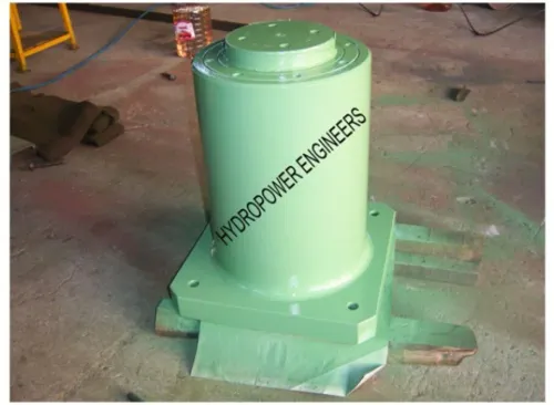
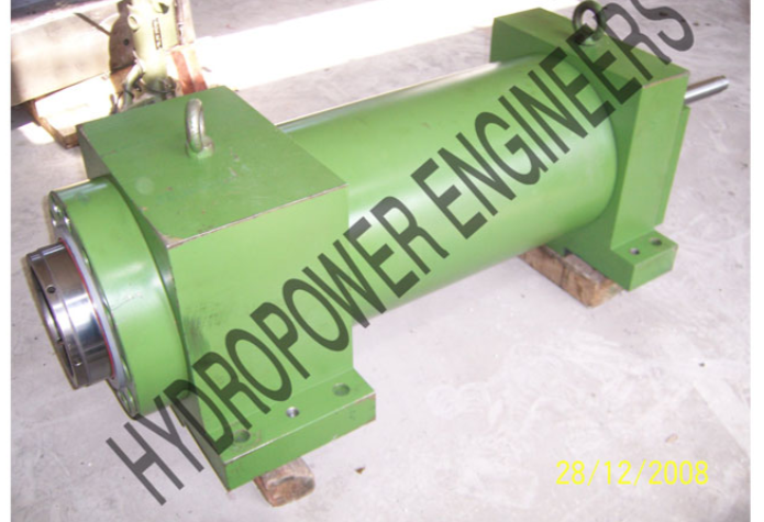 | Hydraulic Cylinders Hydropower Engineering Systems offers robust and high-performance High Tonnage Hydraulic Cylinders designed to deliver exceptional linear force for... View product → |
Frequently asked questions
How do you calculate cylinder force for a squeeze bending machine?
Start with the tool reaction load from tube diameter, wall thickness, material grade, bend radius, tooling geometry, and friction. Then include the squeeze, clamp, or carriage mechanical advantage and size the cylinder from hydraulic pressure and piston area.
When should a machine use push, pull, or opposed-cylinder action?
Use push action when the cylinder drives a tool into the tube, pull action when the actuator retracts a carriage or die, and opposed cylinders when balanced force and controlled alignment are required across the workpiece.
Which high-tonnage cylinder specifications determine usable tonnage?
Compare bore diameter, rod diameter, rated pressure, working stroke, retraction force, speed, mounting style, seal package, rod buckling capacity, side-load tolerance, and fatigue-duty rating.
How should you design the mounting and guide system?
Keep the cylinder force line aligned with the tool reaction line, use suitable clevises or trunnions, and support moving tooling with independent guides. Do not use the cylinder rod to absorb bending or side loads.
What should an automotive tube-work cylinder specification include?
State tube dimensions and grade, tool geometry, force and stroke calculations, cycle rate, pressure, temperature, alignment limits, sensors, safety requirements, inspection documents, and validation tests.