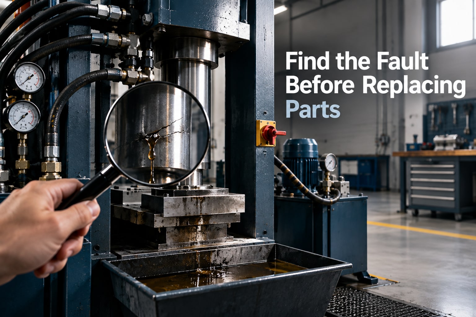
A press that will not start, loses force, drifts under load, moves unevenly, leaks oil, or overheats needs a measured diagnosis before anyone adjusts the relief valve or replaces the pump. By following the symptoms from electrical controls through hydraulics, mechanics, tooling, and safety isolation, you can identify the likely fault and choose a corrective action without turning a minor defect into major hydraulic press repair.
Key takeaways
- Block the ram, bleed trapped pressure, and verify zero pressure before entering the die space.
- Measure pressure and flow separately before replacing a pump, valve, or cylinder.
- Check oil temperature, filter indicators, and leak locations before blaming hydraulic components.
- Inspect alignment, frame deflection, impact marks, and tooling fit after sudden press faults.
Start with Safe Isolation and the No-Start Checks
Treat a sudden loss of ram motion after a burst hose or failed fitting as stored energy, not merely an oil leak. Isolate the main electrical disconnect and hydraulic energy source, mechanically support or block the ram and tooling, bleed trapped pressure, and verify zero pressure before entering the die space.
An emergency-stop button stops controls; it does not prove hydraulic isolation.
For hydraulic press troubleshooting, check the no-start circuit in this order:
- Confirm the electrical isolator is on and the control-voltage fuse is intact.
- Reset the motor overload only after finding why it tripped; a repeated trip points to an electrical or motor fault.
- Check every emergency-stop button, guard interlock, and safety relay for a released and healthy state.
- Read the PLC or drive display for a fault code, and record it before resetting.
- Inspect upper and lower limit switches, ram-position sensors, and selector switches for misalignment or damage.
- Confirm the pump motor contactor engages and the motor rotates in the marked direction.
- Check oil level, suction-shutoff position, and any low-level switch that prevents starting.
Do not raise the relief-valve setting to force a start. Compare its setting with the machine rating and the lowest-rated hose, fitting, cylinder, and tooling before adjustment; excess pressure can overload the frame.
Separate No Pressure, Low Pressure, and Low Flow
A running power unit does not prove the press can build force. Classify the symptom before changing a relief valve: no pressure means the circuit is not generating or retaining pressure; low pressure means it reaches a value below the setting; low flow means pressure is available but the ram moves too slowly.
| Symptom | What to check | Likely cause |
|---|---|---|
| No pressure | Check pump rotation, oil level, suction restriction, tank breather, unloading valve, and relief-valve setting | Wrong rotation, blocked suction, low oil, open unloading, or failed pump |
| Low pressure | Measure pressure at the cylinder inlet and compare it with the relief-valve setting | Relief-valve fault, worn pump, directional valve not fully shifted, or internal leakage |
| Low flow | Record ram speed, cycle time, oil temperature, and measured flow | Pump-speed loss, restricted valve opening, viscous oil when cold, or leakage that increases as oil heats |
If the gauge reaches the rated setting but force remains low, verify gauge accuracy and calculate force as pressure multiplied by effective piston area. Use rod-side annular area during retraction; friction, eccentric tooling, and the stroke position reduce actual force.
Secure the ram and tooling, isolate electrical and hydraulic energy, relieve trapped pressure, and verify zero energy before testing. A frame press fault can be mechanical: binding guides, uneven die contact, or off-centre loading can slow motion and damage seals without abnormal hydraulic pressure. Record the readings before correcting these hydraulic press operating problems.
Diagnose Ram Drift, Jerky Motion, Noise, and Pressure Decay
Hydraulic press troubleshooting starts by locating where pressure disappears, not by replacing the cylinder. A drifting ram points to a load-holding fault, but it does not automatically prove failed seals.
Before entering the die space, isolate electrical and hydraulic energy, mechanically support the ram and tooling, relieve trapped pressure, and verify zero energy. Fit gauges at the cylinder ports and power-unit outlet.
Match the test result to the likely failure:
- If drift stops when the directional valve is isolated, inspect spool leakage, pilot-operated check-valve contamination, and counterbalance-valve pilot pressure.
- If cylinder-port pressure decays while the valve holds, test piston seals and confirm that the external load does not exceed circuit holding capacity.
- If pressure falls at both test points, investigate pump leakage, an unloading valve, or relief-valve leakage.
Jerky travel points to trapped air, restricted suction, a sticky directional-valve spool, or mechanical binding. Bleed the cylinder, check oil level and suction-hose condition, then run unloaded while recording inlet pressure.
Pulsating pressure with speed variation indicates air ingestion or pump wear; steady pressure with uneven travel indicates scored guides, nonparallel platens, rod side-loading, or eccentric tooling.
Whining or crackling signals cavitation; check the tank breather, inlet restriction, and collapsing suction hose. A sharp reversal knock indicates trapped air, loose fittings, or abrupt load-holding-valve closure. Frame press faults also require mechanical inspection.
Never raise relief pressure to cure drift or force loss. Compare the measured setting with the lowest-rated component and manufacturer’s working pressure first.
Trace Oil Leaks, Overheating, and Contamination Before Replacing Parts
Trace the leak to its source before tightening fittings or ordering seals. A sudden oil loss can remove load-holding pressure, so hydraulic press repair begins with electrical and hydraulic isolation, ram blocking, trapped-pressure relief, and zero-energy verification; an emergency stop is not isolation.
1. Clean the area, run a controlled cycle, and mark fresh oil at the hose, fitting, cylinder rod, manifold, or valve. Never enter the die space to inspect a press supported only by hydraulic pressure.
2. Check rising temperature at the reservoir and both cooler lines. Continuous relief-valve bypass, a pump working against a closed-center valve, cylinder leakage, wrong motor speed, high-viscosity oil, or an undersized cooler converts power into heat.
3. Read filter differential pressure and inspect removed media with a magnet or microscope. Bright metal suggests pump, cylinder, bearing, or valve wear; elastomer fragments point to seal damage; water promotes corrosion and additive loss. Oil colour alone proves little.
4. Inspect the suction strainer, inlet hose, tank breather, oil level, and return outlet before replacing a pump. Whining suggests cavitation from restriction or thick oil; foam and erratic motion suggest aeration from suction leaks or return flow above the surface.
Record pressure, temperature, filter condition, and debris source. Repeated hydraulic press operating problems need evidence-led correction, not repeated parts replacement.
Check Alignment, Frame Deflection, Impact, and Tooling Errors
A frame press fault is mechanical or process-related when the ram binds, guide surfaces score, or die contact is uneven while pressure and flow remain normal. These frame hydraulic press problems point to side loading, nonparallel platens, unequal guide wear, a distorted bolster, or tooling that is not seated flat.
- Stop the cycle, isolate energy, block the ram and tooling, and verify zero stored energy before entering the die space. An emergency stop does not isolate hydraulic pressure.
- Inspect guide surfaces, rod and seals for scoring, then measure platen parallelism and check the bolster with a straightedge. Do not increase pressure to overcome binding; eccentric loading can damage guides, rods, and seals.
- Remove the workpiece and run an unloaded stroke. If motion becomes smooth, check die clearance, punch-to-die concentricity, lubrication, tube location, tube ovality, and die wear.
- Compare a defective part with one made on a known-good setup. Wrinkling, tearing, buckling, or asymmetric forming usually identifies a tooling or workholding error.
- Confirm the force calculation uses effective piston area. Retract force uses rod-side annular area, and friction plus tooling eccentricity reduces the usable force even when the gauge reaches rated pressure.
A ram that creeps still needs valve, trapped-air, thermal-contraction, and external-load checks; do not condemn the cylinder seal automatically.
Use Recorded Measurements to Choose the Right Repair
Do not raise the relief-valve setting until you have recorded the manufacturer’s rated working pressure and the lowest-rated hose, fitting, cylinder, frame, and tooling component. A higher setting can overload the machine without increasing its safe capacity. Hydraulic press troubleshooting needs measurements taken at the cylinder inlet, not only the power-unit gauge.
- Record pressure, flow, cycle time, oil temperature, oil level, filter indicator position, and the ram position when the fault occurs.
- Photograph leaks, scored guide surfaces, die contact, hose routing, gauge readings, and any frame or platen deflection.
- Calculate expected force from pressure × effective piston area; use rod-side annular area during cylinder retraction.
- Record drift distance over a fixed time, pilot pressure at load-holding valves, and the relief setting before adjustment.
| Evidence | What it means | Repair decision |
|---|---|---|
| Measured cylinder pressure and flow | Separates pump, valve, restriction, and gauge faults | Adjust or rebuild the hydraulic circuit |
| Pressure, area, and force calculation | Exposes wrong gauge readings or incorrect capacity assumptions | Correct the calculation or cylinder selection |
| Alignment, deflection, drift, and oil records | Shows mechanical loading, valve leakage, contamination, or seal damage | Repair guides and tooling, rebuild components, or redesign |
Give Hydropower Engineers these records when requesting hydraulic press repair; they can compare the data with the press design instead of replacing parts based on symptoms alone. Never collect measurements inside the die space until electrical and hydraulic energy is isolated, trapped pressure is relieved, and the ram is mechanically supported.
Related products
 | Hydraulic Presses The H-Frame Press is a machine powered by high-pressure fluid, used for shaping materials through applied force. View product → |
 | Hydraulic Presses We are a leading and well-recognized manufacturer of C-Frame Hydraulic Presses, widely used in applications such as embossing, punching, piercing,... View product → |
Frequently asked questions
What should you do before troubleshooting a frame hydraulic press problem?
Isolate the main electrical disconnect and hydraulic energy source, support or block the ram and tooling, bleed trapped pressure, and verify zero pressure before entering the die space.
How do you distinguish no pressure, low pressure, and low flow?
Connect a calibrated pressure gauge at the correct test point, compare pressure with the machine specification, and test flow at operating temperature. Pressure identifies force capability; flow identifies ram speed.
What causes ram drift, jerky motion, noise, or pressure decay?
Check for cylinder seal bypass, valve leakage, air in the oil, restricted suction flow, damaged hoses, contaminated valves, and a pressure-relief valve that cannot hold its setting.
What should you check before replacing parts for leaks or overheating?
Find the exact leak source, inspect fittings and seals, check oil level and viscosity, read the filter restriction indicator, measure oil temperature, and look for contamination in the reservoir and filter.
How can alignment and tooling errors create frame press faults?
Inspect ram-to-bed alignment, die seating, uneven contact, frame deflection, impact marks, loose fasteners, and tooling that exceeds the press capacity or applies an off-centre load.