A high-volume swaging quotation is incomplete if it gives only nominal diameter, tonnage, or stroke rate. By the end, you will be able to compare machine arrangements, calculate usable output and hydraulic demand, and write an acceptance specification that matches your actual tube grades and production schedule.
Key takeaways
- Specify diameter, wall thickness, length, tolerance, and ovality by product family.
- Match rotary, push, or draw swaging to the reduction schedule and part geometry.
- Calculate usable capacity from force, stroke, cycle time, tooling, and material limits.
- Require material trials, guarded tooling, pressure data, and documented acceptance tests.
Which dimensions belong in a high-volume swaging specification?
Before comparing machines, require a capacity matrix, not one nominal pipe size. Pipe swaging machine specifications in Chennai should state maximum and minimum workpiece outside diameter, supported wall-thickness range, solid-rod diameter range, maximum and minimum workpiece length, finished-diameter range, dimensional tolerance, and maximum ovality for each product family.
| Capacity item | Hollow tube | Solid rod |
|---|---|---|
| Governing limit | Wall thickness, bore, unsupported length and buckling | Rod diameter, material strength and reduction per pass |
| Required output | Final outside and inside diameter | Final outside diameter |
| Equal outside diameter | Does not prove equal forming capacity | Does not prove tube capacity |
For every important part, request:
- Starting diameter, finished diameter, wall thickness, material grade, number of operations, forming force or pressure, cycle time, and expected quality.
- Acceptance limits for final inside diameter, minimum wall thickness, concentricity, end-face condition, surface damage, length tolerance, allowable dimensional tolerance, and maximum ovality.
- Mandrel diameter, support length, die clearance, die-entry geometry, and lubrication method. Internal support controls ovality, wrinkling, local buckling, and bore restriction.
- Maximum and minimum workpiece length, plus the solid-rod range as a separate figure from hollow-tube capacity. A rod and tube with the same outside diameter do not impose the same forming load or stability requirement.
Which swaging arrangement fits the part and reduction schedule?
Rotary swaging fits solid rods, short components, and progressive reductions; long tubes usually need linear or axial feeding, while localised stepped ends suit hydraulic press-style forming.
| Arrangement | Loading and tooling action | Best fit and checks |
|---|---|---|
| Rotary swaging | Radial dies or hammers act around the workpiece | Solid rods, short parts, progressive reductions; verify die stations, feed length, and reduction per pass |
| Linear or axial swaging | The tube advances into closing tooling | Long tubes and controlled end reductions; check unsupported length, die opening, and axial travel |
| Axial tube-end forming | A press closes dies around a supported end | Short local reductions and stepped profiles; match die set and mandrel to each shoulder |
| Tube-reducing equipment | The tube feeds through reducing dies, often with internal support | Continuous or repeated diameter reduction; confirm wall-thickness control and pass count |
Compare solid-rod capacity and hollow-tube capacity separately. The same outside diameter does not mean the same machine suitability: wall thickness, unsupported length, and buckling resistance govern tube forming.
A practical cycle is:
- Load and align the workpiece.
- Insert the mandrel and feed axially.
- Close the dies or start hammer action.
- Complete the reduction, withdraw the part, and open the dies.
- Inspect diameter, ovality, bore, and surface condition.
Confirm whether the machine performs cold swaging, hot forming, or both; do not infer temperature from tube-upsetting equipment. For rod pipe tube swaging machine specs, demand separate production examples for a solid rod, a long hollow tube, and a stepped tube end.
How do you calculate usable pipe swager capacity?
Calculate usable capacity from net accepted parts per hour, not from stroke rate alone. Start with the actual material grade, temper or heat treatment, starting outside diameter, wall thickness, tube length, finished diameter, reduction per operation, and required number of passes.
1. Define the production route. Record forming time, axial feed and return, loading, unloading, indexing, die opening, lubrication, inspection, changeover, and tool changes. A long tube with several reductions can consume more time in handling and tooling than in the forming stroke.
2. Calculate the full cycle. Divide available production time by the complete cycle time, then deduct the scrap allowance. Net accepted pieces per hour equals accepted output from the full production cycle; it does not equal stroke rate multiplied by an ideal shift.
3. Verify the result with production-intent tubes and tooling. During a representative run, record sustained output, ovality, minimum wall thickness, bore condition, operator interventions, and tool consumption. An unloaded demonstration at advertised stroke rate proves no high-volume capacity.
Use this quotation table for each major product family:
| Material | Starting size | Final size | Wall thickness | Stroke rate | Number of operations | Cycle time | Scrap allowance | Sustained accepted output |
|---|---|---|---|---|---|---|---|---|
| Actual grade and temper | Outside diameter | Finished diameter | Millimetres | Strokes/minute | Passes | Seconds/part | Percentage | Accepted parts/hour |
For pipe swager capacity in Chennai, demand this capacity matrix rather than a maximum-diameter claim. A machine must maintain quality and output across the stated diameter, wall-thickness, material, and length ranges. Include changeover time and tool-life evidence in the commercial comparison.
What pressure and hydraulic power does the machine need?
Pressure at the power pack is not the force available at the workpiece. For a hydraulic cylinder, ideal force is F = P × A: a 100 mm-bore cylinder at 200 bar produces about 157 kN theoretical extension force before losses.
Separate system pressure, forming force, clamping force, and pressure needed to overcome material resistance and friction.
| Term | What it tells you | What to verify |
|---|---|---|
| Pump relief pressure | Maximum circuit setting | Is it relief pressure, normal operating pressure, or actuator pressure? |
| Forming-cylinder pressure | Pressure at the actuator | Subtract valve, hose, and piping losses from power-pack readings |
| Forming force | Cylinder force applied to the part | Calculate from bore, pressure, and efficiency |
| Clamping force | Force preventing slip or movement | Confirm it suits wall thickness, mandrel friction, and alignment |
Size the system from required force, cylinder bore, operating pressure, flow rate, stroke, cycle time, motor power, accumulator volume, and duty cycle. Add margin for the material grade, reduction schedule, mandrel friction, alignment, and lubrication.
Tube swaging machine pressure requirements also cover continuous oil control. Ask for reservoir volume, filtration rating, cooler capacity, permissible oil-temperature range, and pressure stability at production speed; undersized cooling causes force and dimensional drift as oil heats.
Require the electrical schedule, not an unspecified power-pack rating:
- 415 V, three-phase, 50 Hz site supply where applicable
- Allowable voltage variation, control voltage, earthing arrangement, short-circuit rating, and connected load
- Ambient-temperature and enclosure limits for the installation
How should you qualify materials, tooling, safety, and the supplier?
Qualify the quoted machine with production-intent material, tooling, and a sustained acceptance test—not an unloaded demonstration or a generic tonnage claim.
1. Test the actual carbon steel, stainless steel, aluminium, copper alloy, or high-strength tube grade in its production temper and heat-treatment condition. Record the reduction schedule, mandrel diameter and support length, die-entry geometry and clearance, die material and heat treatment, lubricant, alignment method, and scale-control method.
Strength and work-hardening can change forming force more than a small diameter change.
2. Request tool life in accepted parts per die set. Define replacement by a measurable limit, such as ovality, bore restriction, surface scoring, dimensional drift, or a specified number of accepted parts; “long-life tooling” is not an acceptance criterion.
3. Run production-intent tubes and tooling for a sustained acceptance test. Record accepted output, dimensional capability, ovality, inside diameter, minimum wall thickness, surface damage, hydraulic pressure, oil temperature, noise, changeover time, tool consumption, and operator interventions.
4. For a Chennai installation, specify enclosure and ambient-temperature limits, die guarding, pinch-point protection, emergency stops, restart prevention after power recovery, hydraulic stored-energy isolation, and a safe tool-change mode. Use ISO 4413 for hydraulic safety and ISO 12100 for machinery risk assessment.
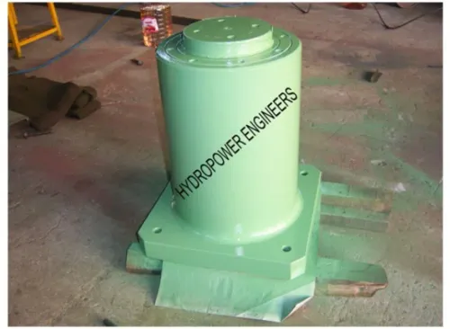
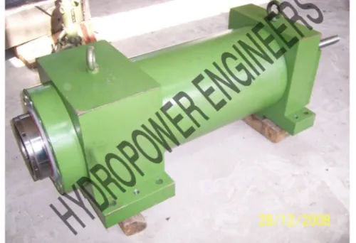
Evaluate Hydropower Engineers against a capacity matrix, documented trials, hydraulic calculations, tooling data, and site-ready electrical and safety documents.
Related product
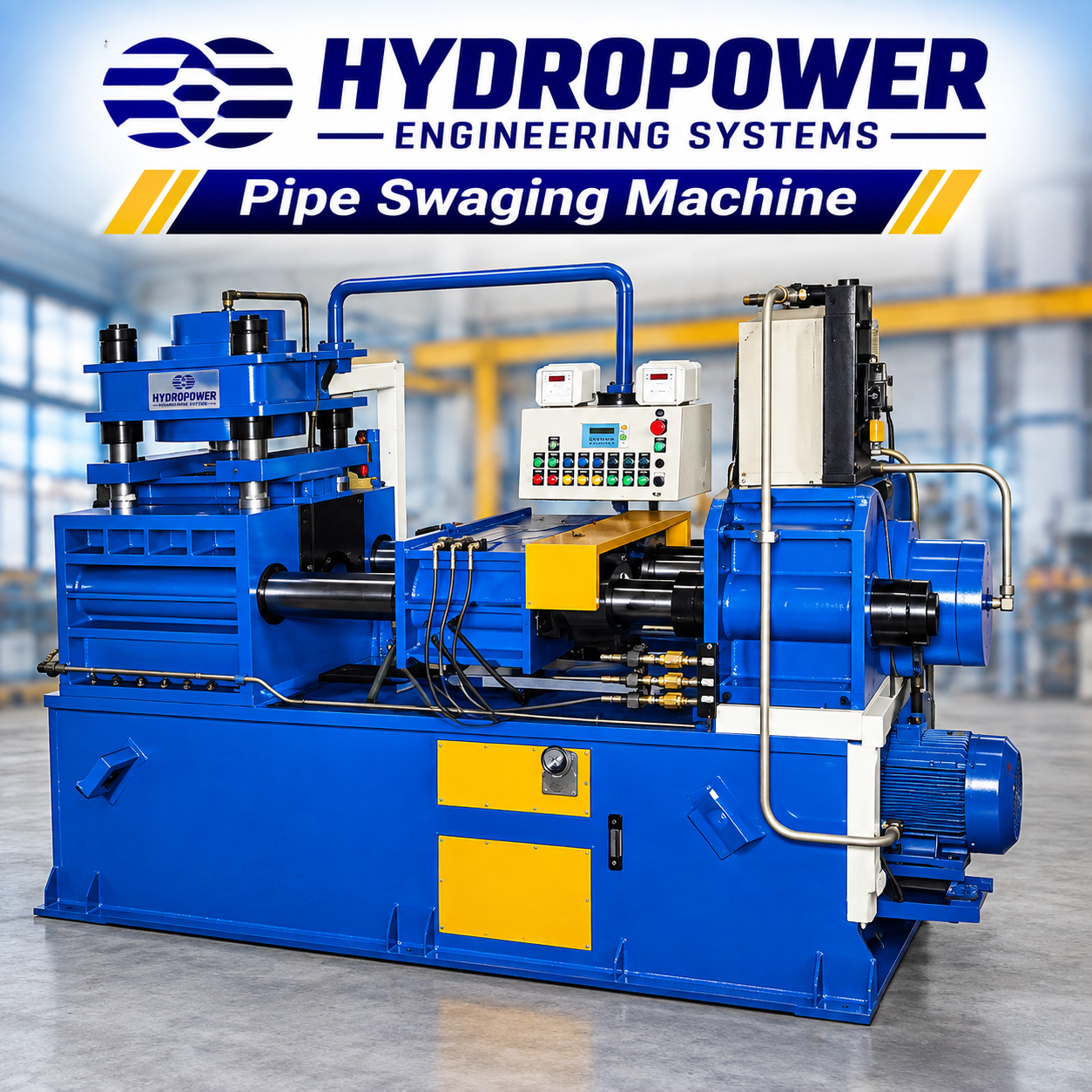 | Pipe Swaging Machine Hydropower Engineering Systems manufactures robust and efficient Pipe Swaging Machines designed to reduce the diameter of pipes and solid rods to the... View product → |
Frequently asked questions
Which dimensions belong in a high-volume pipe swaging specification?
State maximum and minimum workpiece outside diameter, wall-thickness range, solid-rod diameter range, workpiece length, finished-diameter range, dimensional tolerance, and maximum ovality for each product family.
Which swaging arrangement fits the part and reduction schedule?
Choose rotary swaging for repeated radial reduction and round sections, push swaging for controlled axial reduction, or draw swaging when a die must size the outside diameter and improve repeatability. Check the number of passes, reduction per pass, end geometry, and required feed or extraction method.
How do you calculate usable pipe swager capacity?
Calculate capacity from the supported diameter and wall-thickness envelope, available stroke, feed length, tooling clearance, cycle time, number of passes, setup time, and the actual material reduction schedule. Use the slowest product family and include time for loading, unloading, inspection, and tool changes.
What pressure and hydraulic power does a tube swaging machine require?
Specify cylinder bore, operating pressure, peak pressure, flow rate, stroke speed, and duty cycle. Estimate hydraulic power from pressure and flow using P in kilowatts equal to pressure in bar multiplied by flow in litres per minute, divided by 600, then allow for efficiency and peak loads.
How should you qualify a pipe swaging machine supplier?
Run trials using your production material, starting dimensions, tooling, reduction schedule, and target cycle time. Record finished dimensions, ovality, surface condition, force or pressure trace, cycle time, tool life, guarding, emergency stops, and acceptance-test results.