A rotary swager is suited to localized tube forming, but the correct choice depends on the end profile, reduction length, wall thickness, bore control and downstream operations. By mapping the process and comparing it with drawing, spinning, pressing, roll forming and machining, you can identify when swaging adds value and when another method is safer.
Key takeaways
- Use radial die blows to reduce tube diameter or form stepped profiles.
- Place rotary swaging before finishing, heat treatment, or final machining.
- Choose mandrel control for accurate internal diameters and wall thicknesses.
- Specify tube material, dimensions, reduction, feed rate, and die configuration.
How a rotary swager changes a tube
A rotary swager machine changes a tube through repeated radial blows from two, three or four dies, not through one pressing stroke. As the workpiece rotates, feeds axially, or does both, the dies deliver incremental cold-forged deformation and move metal by plastic flow.
The resulting geometry depends on the tooling and support:
- Reduce the outside diameter over a short section.
- Control the inside diameter with a solid mandrel supporting the bore.
- Produce a stepped or tapered transition.
- Form a pointed, rounded, or otherwise shaped nose.
These outcomes are not interchangeable. Closing or thickening a tube end adds material to the wall or compresses the opening; it is not the same as reducing the outside diameter. Chamfering only removes or shapes the edge, leaving the main tube geometry unchanged.
Localized end forming is the rotary swager’s strongest use case. It creates a short reduced, tapered, stepped, or shaped zone without drawing the full tube length through a fixed die. That suits fitting seats, spigots, joining ends, and later machining preparation.
Material removal is low because the process forms rather than cuts the metal. Plan for follow-up work when needed: cutoff burr removal, trimming, piercing, or final sizing can still be necessary, especially where the swaged end meets a seal or precision fitting.
Where swaging belongs in the tube process route
Use rotary swaging after the tube has been prepared and any long, uniform reduction has been completed. A practical route is:
1. Cut the tube to length, then remove scale, oil and chips. Contamination can score the dies or become trapped in a fitting seat.
2. Anneal the tube when the alloy or accumulated cold work leaves too little ductility for the next reduction. Skipping this step can produce cracks or a split transition.
3. Point the end when a draw bench needs a smaller gripping lead. A rotary swager for tubes can reduce the end for a subsequent drawing operation without machining away most of the material.
4. Draw the long section when the finished part requires a continuous reduction with controlled cross-section. Do not use rotary swaging for a long, uniform reduction across the entire tube.
5. Use rotary swaging for the localized feature: a short reduction, taper, step, spigot, pointed nose, sleeve, fitting seat, or brazed or joined end. Successive diameters are a strong reason to choose it over a single fixed-die operation.
6. Place upsetting separately when the objective is to increase end wall thickness for machining, threading or material retention. Upsetting adds material to the end zone; it is not simply an outside-diameter reduction.
7. Chamfer after forming when the requirement is only a deburred or angled edge. Apply final sizing after swaging when a seal or fitting needs a controlled outside or inside interface.
When rotary swaging beats drawing, pressing and machining
Choose tube drawing for a long, continuously reduced section and a highly controlled cross-section; choose rotary swaging when reduction stays at an end or includes several short diameters and tapers.
| Option | Geometry match | Main trade-off |
|---|---|---|
| Tube drawing | Long, uniform reduction through a fixed die | Strong cross-section control, but the entire tube needs a gripping lead and draw length |
| Rotary swaging | Short ends, steps, spigots, tapers and successive diameters | Low scrap and localized forming, but dedicated dies add changeover time |
| Spinning | Rotationally symmetric shapes over a longer surface | Smooth contours, with slower setup for short production runs |
| Press reduction | Simple single-stroke shapes with accessible loading | Fast loading, but less suited to several transitions |
| Roll forming | Continuous profiles along the tube | High throughput, but poor fit for isolated end features |
| Machining | Removed material or a precise internal feature | Tight detail, but higher scrap and cycle time |
| Upsetting | Ends that must gain wall thickness | Retains material at the end rather than reducing its outside diameter |
A rotary swaging machine uses radial die motion around the workpiece. Two, three or four dies strike repeatedly while the tube feeds, rotates, or does both through an incremental forming zone; a linear swager uses opposing tooling movement along a linear layout with a different die arrangement.
Rotary swaging often improves throughput and surface finish for repeatable ends, while holding useful tolerances with little material removal, but tooling changes cost time.
Choose another process for very long uniform reductions, brittle alloys, unsupported ultra-thin walls, or profiles that change too often to justify dedicated dies.
Which tubes and profiles need mandrel control
Mandrel control is necessary when the finished bore, wall distribution, or concentricity matters. Check the alloy and temper first: low-ductility or heavily cold-worked material can crack at the transition, while ductile material tolerates greater reduction before annealing becomes necessary.
Confirm these geometry inputs before choosing an industrial rotary swager:
- Starting outside diameter, inside diameter or wall thickness
- Finished outside and inside dimensions
- Reduction length and number of passes
- Taper angle, straight sections, and tapered transitions
- Round or non-round profile
- Allowable ovality, eccentric wall, and concentricity
A solid mandrel supports the bore and controls final inside diameter and wall-thickness distribution. Without one, the bore can close or change; use that method only when the internal dimension does not require control.
| Mandrel choice | Result | Suitable use |
|---|---|---|
| Solid mandrel | Supports the bore and controls ID and wall flow | Controlled tube dimensions |
| No mandrel | Bore may close or shift | Non-critical internal dimensions |
Thin-wall tube needs validation, not a nominal diameter check. Incorrect mandrel clearance, entry geometry, axial support, or unsupported length can cause ovality, local collapse, wrinkling, or eccentric wall.
Wall thickness will not automatically remain constant. Die and mandrel profiles, feed rate, reduction per pass, friction, and material flow all change it, so measure wall thickness around the clock positions.
Cold work raises hardness and residual stress. Specify an intermediate or final anneal when later flaring, bending, or expansion could exceed the alloy’s ductility. Round sections are easiest to support; non-round profiles need dedicated tooling and trials to confirm corner filling and dimensional stability.
What to specify before buying an industrial rotary swager
Do not approve an industrial rotary swager from nominal tube diameter or spindle power. Base acceptance on the complete part drawing and process route, because die profile, mandrel geometry and material flow determine the finished tube.
- Alloy and temper; starting and finished OD, ID and wall thickness
- Formed length, number of passes, and allowable reduction per pass for that material
- Taper, step or spigot profile, including transition length
- Mandrel diameter and profile
- Maximum ovality, concentricity and straightness
- Surface-finish limits and restrictions on die marks
- Lubricant type, application method and cleaning method
- Heat treatment between passes or after forming
- Manual or automated loading and unloading
2. Require sample trials on your actual tube. Record OD, ID and wall thickness at several clock positions, plus ovality, concentricity, transition length and surface condition. Inspect every sample for die marks, scoring, galling, circumferential ridges, cracks, end flare, mandrel sticking and residual burrs.
3. Ask for documented tooling life, die and mandrel changeover requirements, inspection gauges and the allowable reduction per pass for your alloy and temper. Reject a general reduction ratio as proof of tolerance; rotary swaging does not guarantee constant wall thickness.
Hydropower Engineers in Chennai is worth approaching when the line also needs customized hydraulic or material-handling integration, but begin with the part drawing, loading method and process route—not the machine name alone.
Related product
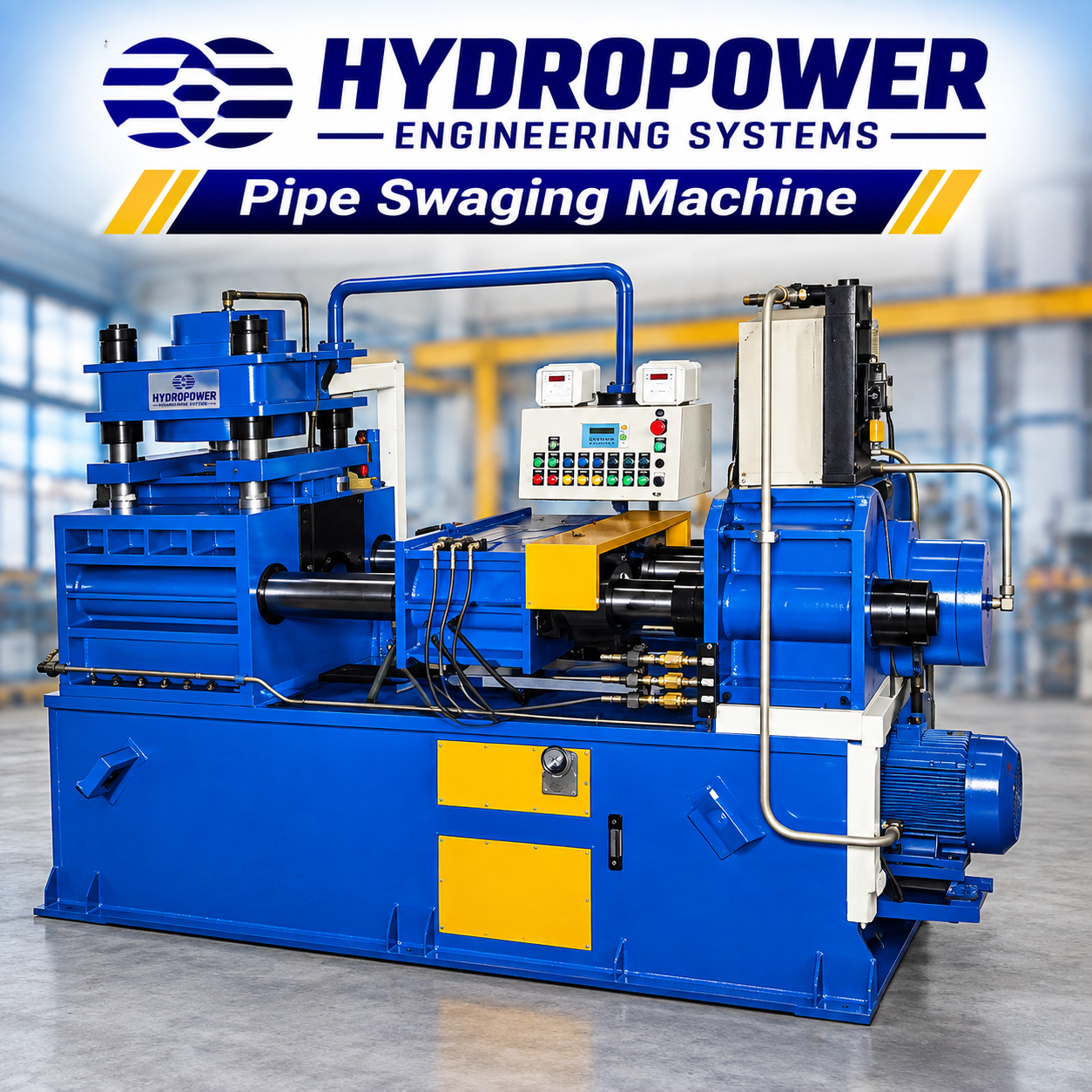 | Pipe Swaging Machine Hydropower Engineering Systems manufactures robust and efficient Pipe Swaging Machines designed to reduce the diameter of pipes and solid rods to the... View product → |
Frequently asked questions
How does a rotary swager change a tube?
Two, three, or four dies deliver repeated radial blows while the tube rotates, feeds axially, or does both. The metal deforms through plastic flow rather than one pressing stroke.
Where does rotary swaging belong in a tube process route?
Use it as a forming operation before finishing, heat treatment, or final machining when the tube needs diameter reduction, tapering, steps, or a shaped end.
When does rotary swaging beat drawing, pressing, or machining?
Rotary swaging suits incremental diameter reduction, tapered transitions, short formed zones, and hollow parts where drawing, pressing, or machining would require more tooling or remove material.
Which tubes and profiles need mandrel control?
Use mandrel control when the internal diameter, wall thickness, concentricity, or internal profile must remain within a defined tolerance during reduction.
What should you specify before buying an industrial rotary swager?
Provide material grade, starting and finished dimensions, wall thickness, reduction length, profile geometry, production rate, feed method, die count, and required tolerances.