A squeeze bending machine cylinder must generate the required forming and clamping forces without buckling, skewing the tooling, or losing control of the tube. By the end, you will be able to calculate the required tonnage, select bore and stroke, assess mounting and load-holding needs, and write a purchasing specification that matches production duty.
Key takeaways
- Calculate force from the projected bend area and required forming pressure.
- Add a documented safety margin after calculating peak working force.
- Match cylinder stroke, speed and duty cycle to the production sequence.
- Keep the cylinder force line aligned with the tooling load path.
What the Cylinder Does During Squeeze Bending
During loading, the squeeze bending machine cylinder remains retracted so the die and clamp open. The operator or loader places the tube against the bend die, with its end and seam positioned as the tooling requires.
- Clamping: The cylinder advances the clamp or pressure die until it holds the tube against the bend die. It must provide enough holding force to prevent slipping without crushing or marking the wall.
- Squeezing: The cylinder continues applying force as the pressure die pushes the tube into the bend die. This compression helps form the bend and controls ovality, wrinkling, and wall collapse.
- Forming: A hydraulic cylinder for bending may maintain force while another tool rotates, translates, or completes the bend. The cylinder follows the tooling movement only within its designed stroke; it is not a substitute for guided tooling.
- Release: After the bend reaches its programmed position, pressure is held long enough for the material to settle. The cylinder then retracts, removes clamp load, and clears the tube for unloading.
The cylinder should carry axial forming force, not substantial transverse force or bending moment. Guides, sliding platens, columns, or spherical mounts must react those loads; otherwise the rod can score, the gland can wear, and seals can fail.
For a double-acting cylinder, extension and retraction do not produce equal force. Retraction loses the rod area, so a machine using the same cylinder to close and open tooling may have a weaker return stroke.
Calculate Force, Tonnage and the Required Safety Margin
Size from the peak forming load, not the average bending load. Establish that load for the actual tube and tooling arrangement using calculation, a validated simulation, or a load-cell test. Include:
- Tube outside diameter, wall thickness, material yield strength and bend radius
- Draw, compression or squeeze-bending method
- Die geometry, contact area and friction
- Clamp force and any simultaneous tooling load
- Hydraulic pressure available after pump, valve, hose and filter losses
Use F = P × A. For a piston-side stroke, A = πD²/4; for retraction, subtract rod area: F = P × π(D² − d²)/4. Retraction force is therefore lower, even with the same pressure.
For example, assume a 60 mm outside-diameter tube with a 3 mm wall, 350 MPa material yield strength, a 90 mm centreline radius and squeeze tooling. A validated load estimate gives 180 kN forming force plus 40 kN clamp force: 220 kN total. Add a 20% margin, producing a 264 kN design force.
At 160 bar nominal pressure and 15 bar circuit loss, effective pressure is 145 bar. The required piston area is 264,000 ÷ 14.5 million = 0.0182 m², giving a calculated bore of 152 mm; select the next practical bore, such as 160 mm, then verify its actual force.
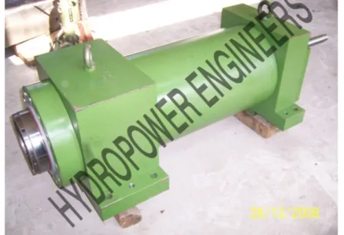
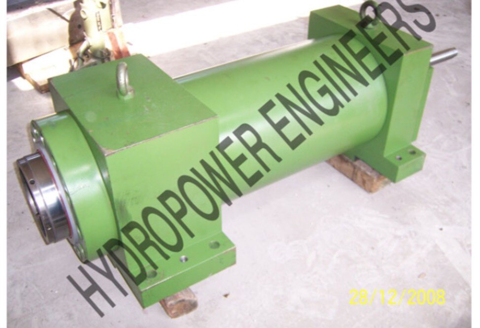
A high tonnage hydraulic cylinder must also pass rod-buckling and mounting checks. Keep transverse force in guides or columns, and specify filtration and cleanliness because contamination can mimic inadequate cylinder force.
This is the basis for selecting a high tonnage cylinder for squeeze bending machine rather than choosing a high tonnage hydraulic cylinder by tonnage alone.
Choose Stroke, Speed, Circuit Protection and Production Duty
Set the stroke to cover the full tooling movement without using the piston as a hard stop. Measure closed-tool and open-tool positions, add setup clearance, then specify cushion length at both ends; unused stroke increases oil volume, cycle time and buckling risk.
Separate approach, forming and return speeds. Use fast approach until the tooling contacts the tube, a controlled forming speed through material deformation, and a faster return only after pressure is released. Specify each speed in millimetres per second, plus acceleration and dwell time. A fast approach does not make a fast bend.
Circuit protection must match the load direction and failure consequence.
| Option | Purpose | When it applies |
|---|---|---|
| Pilot-operated check valve | Holds the cylinder if valve centre shifts or a hose fails | Resisting loads that must stay in position |
| Counterbalance valve | Controls overrunning motion and prevents runaway descent | Loads that can drive the cylinder |
| Relief valve and pressure switch | Limits spikes and stops an overload cycle | Every high-tonnage hydraulic cylinder circuit |
Mount load-holding valves close to the actuator. Do not rely on a directional valve’s centre condition alone.
Specify the production duty, not just “automotive hydraulic cylinder.” Give the manufacturer:
- Cycles per shift and total life target
- Cycle frequency, force-time profile and pressure dwell
- Stroke utilisation and permissible pressure spike
- Oil grade, temperature range, filtration level and leakage limit
- Working pressure, proof pressure and assembly rating
A proof-pressure test demonstrates structural resistance; it does not authorise continuous operation at that pressure. A cylinder suitable for intermittent fabrication can fatigue or lose seals in continuous production.
Match the Mounting Arrangement to the Tooling Force Line
Put the tooling force line through the cylinder’s piston centreline and keep transverse loads out of the rod. A squeeze bending machine cylinder should push or pull the moving platen, while die guides, columns, or a guided slide resist the bending moment created by the tube and tooling.
| Mounting or guidance feature | Load it should carry | Accuracy and failure benefit |
|---|---|---|
| Guided platen with replaceable wear strips | Transverse force and moment | Prevents rod scoring, seal wear, and platen skew |
| External columns or tie rods | Tooling side load | Keeps the hydraulic cylinder for bending in axial compression |
| Die guides or enclosed tooling | Local die reaction | Holds the bend path and reduces eccentric loading |
| Spherical washer or self-aligning mount | Small angular misalignment | Prevents edge loading at the cylinder connection |
Do not use the cylinder rod as a slide, guide post, or die alignment surface. Even adequate tonnage will not prevent gland damage if an offset tool loads the rod sideways.
Check rod buckling with the actual unsupported extension, rod diameter, peak forming load, and end restraints. A pinned-to-pinned assumption is not interchangeable with fixed or guided ends; use the corresponding effective length in the Euler-type check. Long extension and eccentric loading can buckle the rod before the pressure rating is reached.
Align the mount after the tooling is installed, not from the empty machine frame. Confirm that the platen travels freely through the full stroke and that guides—not hydraulic pressure—hold position during forming.
Compare Cylinder Types and Write the Purchasing Specification
A high-tonnage cylinder for squeeze bending machine duty is the right choice when peak forming force, compact installation and repeated compression matter more than micron-level positioning.
Choose a servo cylinder for closed-loop force or position control; choose a press cylinder when a guided platen and broad, stationary tooling carry the load; choose a telescopic cylinder only when retracted length limits installation and the load path remains well guided.
| Option | Strength | Choose it when |
|---|---|---|
| High-tonnage cylinder | High direct force in a compact body | Peak squeeze load dominates and external guides resist side load |
| Servo cylinder | Precise position, force and speed control | The bend requires programmable profiles and feedback |
| Press cylinder | Works with a rigid platen and frame | Tooling loads pass through columns or a press structure |
| Telescopic cylinder | Long stroke from short retracted length | Installation space is restricted and extension is well supported |
Do not specify an “automotive hydraulic cylinder” by label alone. State the production duty: cycles per hour, expected service life, approach and forming speeds, end-position repeatability, allowable leakage and ambient temperature.
Give the manufacturer a purchasing specification that includes:
- Peak forming and clamping loads, pressure at the cylinder, pressure losses, and separate extension and retraction forces; retraction uses p × π(D² − d²)/4.
- Bore, rod diameter, stroke, effective buckling length, end mounts and actual restraint conditions.
- Guided tooling or platen details proving the cylinder will not carry bending moment or side load.
- Oil type, filtration location, cleanliness target, seals, rod finish and corrosion protection.
- Hydropower Engineers can use these duty figures to check the cylinder against the machine’s real load path rather than its nominal tonnage.
Related product
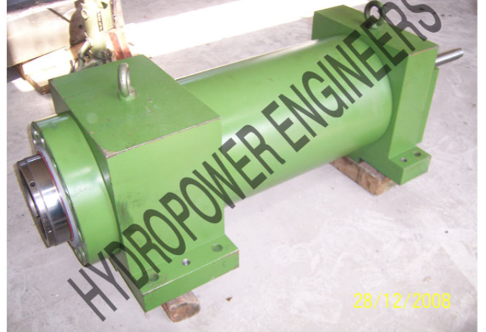 | Hydraulic Cylinders Hydropower Engineering Systems offers robust and high-performance High Tonnage Hydraulic Cylinders designed to deliver exceptional linear force for... View product → |
Frequently asked questions
How do you calculate the tonnage for a squeeze bending machine cylinder?
Calculate the required hydraulic force from the projected forming area and working pressure, then convert the result to tonnes-force and add a documented safety margin.
What cylinder stroke and speed does squeeze bending require?
Choose stroke from the die opening and clamping travel, then set approach, forming and return speeds around the machine cycle and material response.
Why does cylinder mounting alignment matter in squeeze bending?
The cylinder force line must follow the tooling load path; misalignment creates side load, seal wear, rod bending and uneven forming force.
What should a purchasing specification for a high-tonnage cylinder include?
Specify bore, rod diameter, stroke, rated pressure, retraction force, mounting style, cushion requirements, speed, duty cycle, hydraulic fluid and inspection documentation.