A press brake needs more than a motor that reaches high pressure: it needs controlled oil flow, stable pressure, safe valve operation, and enough cooling for the complete production cycle. By the end, you will be able to relate bending force and ram speed to pump, motor, reservoir, valve, filtration, and control specifications.
Key takeaways
- Match pump flow to ram speed and cylinder area.
- Size pressure from required bending force plus system losses.
- Use separate approach, bending, and return flow strategies.
- Specify filtration, cooling, relief protection, and stable controls.
How a power pack drives each press-brake movement
The motor turns the pump, which draws oil from the reservoir and sends it into the hydraulic press brake circuit. Pump flow determines cylinder and ram speed; hydraulic pressure determines the available bending force.
A relief valve limits maximum pressure by diverting excess oil back to the tank, but it does not replace load-holding or hose-rupture protection.
The power pack changes oil flow for each movement:
- Approach: The pump supplies high flow at lower pressure, moving the ram quickly toward the workpiece. A two-pump, variable-displacement, or regenerative circuit can provide this combination.
- Bending: The circuit reduces flow and raises pressure as the tooling contacts the sheet. Lower flow improves controllability while pressure builds to the force required for the bend.
- Return: The directional valve reverses the oil paths, sending flow to retract the cylinders and returning displaced oil to the reservoir.
A control circuit operates the directional valve from the press controller and coordinates the cylinder movements. The valve manifold routes oil through hoses to the cylinders, while filtration removes particles that could damage pump or valve clearances.
The reservoir stores and cools the oil, and its breather allows volume changes without pulling unfiltered air into the tank.
When the motor stops, blocked lines and cylinder loads can retain dangerous energy. Isolation, pressure release, guarding, and a safety-related control system are therefore part of the complete installation, not optional power-pack accessories.
How to size pressure, flow, pump, and motor
Check the pack against the complete press-brake cycle, not the machine’s nominal tonnage alone. Pressure supplies bending force; flow determines cylinder speed and cycle time.
1. Calculate required pressure. Divide forming force by the combined effective piston area, then add losses from valves, hoses, and synchronization. For a 1,000 kN force and 0.050 m² total piston area, ideal pressure is 200 bar. Specify relief-valve pressure above the working value without exceeding the cylinders’ rated pressure.
2. Calculate flow from speed. Multiply total piston area by desired ram speed. At 0.050 m² and 50 mm/s, flow is 150 L/min. A pack that reaches 200 bar but delivers only 80 L/min will bend with enough force, yet approach and return will take much longer.
3. Match the pump. Check displacement, motor speed, and volumetric efficiency: flow in L/min equals displacement in cm³/rev × rpm × efficiency ÷ 1,000. High-flow, low-pressure approach and lower-flow, high-pressure bending may require two pumps, variable displacement, or regeneration.
4. Check motor power. Use pressure × flow ÷ 600 for hydraulic kilowatts, then divide by total efficiency. The example requires 50 kW hydraulically; losses demand a larger motor rating and suitable duty cycle.
5. Confirm heat control. A fixed-displacement pump needs unloading during dwell; forcing continuous flow across the relief valve overheats hydraulic power systems. For a Bangalore installation, verify supply voltage, ambient temperature, ventilation, oil grade, and service access against the hydraulic power pack’s data sheet.
How the circuit manages approach, bending, and return
The circuit changes both flow and pressure as the ram moves: high flow for approach, controlled high pressure for bending, and high flow again for return. This lets hydraulic power systems deliver speed without sizing the motor solely for the slower forming stroke.
1. The directional valve sends oil to the rodless sides of both cylinders for approach. A two-pump circuit, variable-displacement pump, or regenerative circuit supplies the high flow needed for rapid descent; a pressure setting limits force while the tooling closes the gap.
2. At the programmed changeover position, or when pressure rises to the set threshold, the circuit reduces flow and raises available pressure. The bending pump then maintains the pressure required for forming, while the controller meters each cylinder so the left and right ram positions remain matched.
3. Position sensors, linear scales, or cylinder transducers report both sides to the control system. Proportional valves correct any difference by adding or restricting oil to one cylinder; without that feedback, unequal hose resistance, leakage, or valve response can leave one end of the hydraulic press brake ahead of the other.
4. After the bend, the directional valve reverses flow for return. Counterbalance or pilot-operated check valves prevent a sudden drop, and the controller manages deceleration before the upper beam reaches its home position.
Set the changeover points during commissioning. A hydraulic press brake that approaches too slowly wastes cycle time; one that changes to bending too early heats the oil and can produce uneven bends.
How control stability affects bend quality and machine safety
A bend goes wrong when pressure or flow changes during the stroke. An industrial hydraulic power pack produces repeatable bends only when pressure, cylinder speed, and synchronization remain stable through approach, bending, and return.
Relief-valve chatter or a drifting directional valve changes ram force; unequal flow between cylinders twists the beam and alters the bend angle.
| Circuit | Effect on stability and heat | Main trade-off |
|---|---|---|
| Two-pump | High flow during approach, low flow at bending; reduces motor demand during high-pressure work | More valves, controls, and adjustment points |
| Variable-displacement pump | Matches flow to demand and limits throttling losses | Higher component cost and control complexity |
| Regenerative circuit | Increases approach speed by redirecting return oil | Must switch cleanly before pressure-intensive bending |
Control these conditions before accepting production parts:
- Set the pressure-relief valve below the weakest rated component, then confirm actual pressure at the bending cylinders. An unloading valve lets a fixed-displacement pump unload during dwell; forcing continuous flow across relief converts pressure and flow into heat.
- Keep oil within the pump and valve manufacturer’s specified temperature range. Excess heat lowers viscosity, increases leakage, and causes drift; inadequate cooling shortens seal life.
- Use the specified oil grade and filtration rating, with a visible clog indicator and a bypass setting that does not defeat contamination control. Dirty oil makes valves stick and servo response erratic.
- Apply ISO 4413 controls for isolation, pressure release, stored energy, and unexpected start-up. Add load-holding or hose-rupture protection, guarded danger zones, and a safety-related control system; a relief valve alone cannot support a falling ram.
What to specify when comparing a press-brake power pack
Reject any quotation that says only “high pressure” or lists motor horsepower. Give Hydropower Engineers the press cycle, cylinder bore, stroke, target ram speeds, bending pressure, duty cycle, and control voltage; regional location does not determine pressure or flow.
| Document | What to verify | Acceptance evidence |
|---|---|---|
| Pump and circuit | Displacement or control type, usable flow at operating pressure, rated and maximum pressure, two-pump, variable-displacement, or regenerative arrangement | Measured pressure and flow at approach, bending, and return speeds |
| Power and heat | Motor rating, duty, hydraulic power calculation, reservoir volume, cooling method, noise level | Continuous run at design duty without overheating or excessive noise |
| Oil and cleanliness | Oil grade, filtration rating, filter bypass setting, hose ratings, manifold schematic | Fluid cleanliness report, correct bypass operation, and no leakage at rated pressure |
| Bangalore installation | Electrical supply and frequency, ambient-temperature range, installation altitude, ventilation, service clearances, and spare-seal availability | Site acceptance record confirming connections, cooling, access, and isolation |
Request the factory acceptance test before shipment and repeat critical checks after installation. The test should record flow, pressure stability, cylinder synchronisation, response to relief-valve operation, motor current, oil temperature, and emergency-stop performance. Confirm stored-energy controls: pressure release, lockable isolation, protection against unexpected start-up, and safe access to the reservoir, accumulator, and blocked lines.
Use hydraulic power balance as a cross-check: pressure in bar multiplied by flow in litres per minute, divided by 600, gives hydraulic power in kilowatts before efficiency losses. A hydraulic power pack for hydraulic press brake in bangalore division remains suitable only when its measured cycle performance matches the press, not its location label.
Related product
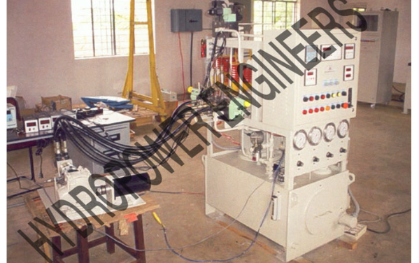 | Hydraulic Power Pack Hydropower Engineering Systems offers high-performance Hydraulic Power Packs designed to meet a wide range of industrial application requirements... View product → |
Frequently asked questions
How does a power pack drive each press-brake movement?
The motor drives the pump, which sends oil from the reservoir to the press-brake cylinders. Flow controls ram speed, while pressure provides the force needed for bending.
How do you size a hydraulic press-brake power pack?
Calculate required cylinder force, select a working pressure below the system’s maximum rating, then size cylinder area, pump displacement, flow, motor power, reservoir capacity, and cooling together.
How does the circuit manage approach, bending, and return?
The circuit uses higher flow for rapid approach, controlled flow and pressure during bending, and a return path sized to retract the cylinders without shock or cavitation.
Why does control stability affect bend quality and safety?
Stable pressure, predictable flow, proportional valves, accurate position feedback, and correctly set relief protection help maintain bend angle while limiting overspeed, shock, and overload.
What should you specify when comparing a press-brake power pack?
Request rated pressure, usable flow, pump type, motor rating, reservoir volume, filtration, cooling, valve configuration, noise data, controls, safety functions, and service documentation.