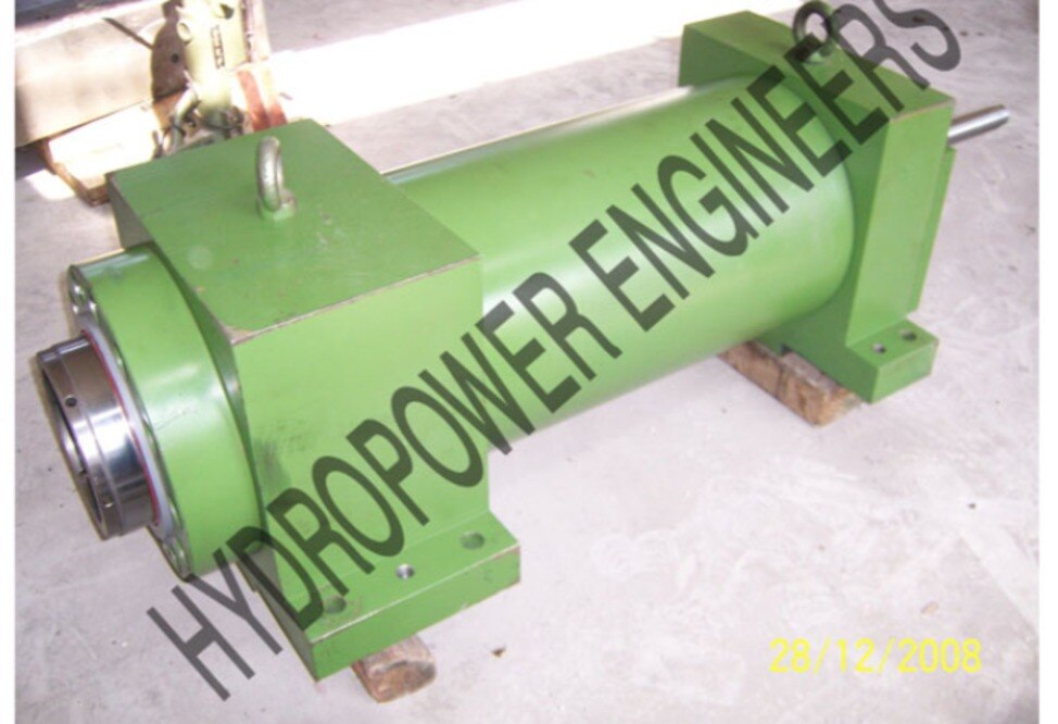
A rotor for an earth drilling machine is not a precise enough description to choose a tube-forming process: the part may be a tubular shaft, sleeve, housing, or drill-stem blank inside a rotary-head assembly. By identifying the component, mapping its manufacturing route, and comparing force, alignment, tooling, and repeatability data, you can decide whether push pointing improves production or adds an unnecessary setup.
Key takeaways
- Use push pointing for suitable tubular shafts, sleeves, housings, and drill-stem blanks.
- Place push pointing after tube preparation and before the next forming or machining operation.
- Check wall thinning, buckling, cracks, and tool alignment before approving production.
- Demand sample parts, forming-force data, dimensions, and inspection results from equipment suppliers.
Which rotor components are suitable for push pointing?
“Rotor for earth drilling machine” is not precise enough for process selection. It may mean the complete rotary-head or drive assembly; push pointing normally applies to a tubular shaft, sleeve, housing, or drill-stem blank that becomes part of that assembly.
Before selecting a push pointing machine for earth drilling rotors, make the drawing state the material grade, outside diameter, wall thickness, overall length, end connection, heat-treatment condition, hardness, straightness, and required runout.
| Process | What it does | Result |
|---|---|---|
| Push pointing | Drives a tube end axially through a converging die | Reduced tapered lead-in |
| Chamfering | Removes only the edge | Welding or assembly clearance |
| Rotary swaging | Reduces the end through repeated radial hammering | Formed smaller end |
| Machining | Removes material as chips | Cut profile or bore |
| Hydraulic upsetting | Compresses material locally | Enlarged section, not a reduced taper |
A suitable blank has ductile tube material, controlled hardness, adequate straightness, enough end length for the required point, and repeatable dimensions. The die and mandrel arrangement must accept that pointed lead-in; poor alignment can send the tube into the drawing die eccentrically and increase runout.
Reject solid shafts, very short ends, brittle or heavily work-hardened material, and blanks requiring complex machined profiles. Low-volume mixed work is also a poor candidate because frequent die changes and setup checks can outweigh the pointing benefit.
Where does push pointing fit in the rotor manufacturing sequence?
The sequence runs from cut tube blank to qualified component: prepare the end, point it, draw it, crop the allowance, then finish-machine the required profile.
- Cut the tube to the blank length and remove burrs, cracked edges, and damaged material.
- Clean off mill scale, rust, weld spatter, and lubricant residue; contamination increases friction and can score the die.
- Heat the stock only when the material grade and approved process require it. Do not treat heating as a substitute for correct tooling or lubrication.
- Push-point the end through a converging die to create a smaller, tapered lead-in.
- Draw or insert the pointed end through the die-and-mandrel arrangement. This is the main productivity benefit of push pointing machine benefits for rotor for earth drilling applications: the reduced lead-in can be gripped by a draw bench or threaded through the tooling.
- Crop the pointed process allowance after drawing. Pointing redistributes metal through plastic deformation instead of turning the whole reduction into chips, but the pointed end usually becomes scrap.
- Machine shoulders, threads, seats, or other final profiles. Pointing can remove a separate long reduced-end machining operation; it does not replace the drawing pass that establishes finished diameter and wall dimensions.
Set point length from grip length, die and mandrel geometry, handling risk, and crop allowance. A short point may fail to enter or grip; an overlong point increases scrap and bending risk.
Inspect pointed diameter, length, taper, transition, and wall condition, then verify post-drawing diameter, wall thickness, straightness, and runout.
What production problems can the process solve—and what can it damage?
A controlled taper solves die-entry failures: the pointed lead-in enters the cold-drawing die without catching its shoulder. Stable pointed-end diameter and length reduce operator shimming and manual adjustment, while repeatable axial alignment limits eccentric entry and downstream runout.
These push pointing equipment benefits matter for tubular rotor parts carrying torsion, bending, axial load, vibration, and abrasive contamination.
- Use integrated workholding to reduce crane, fixture, and re-clamping steps. Store standardized recipes for repeated grades and sizes to shorten setup, but verify each recipe after a die, lubricant, material, or stroke change.
- Inspect the pointed profile and transition after setup changes, not only the finished tube. Check for thinning, folding, laps, scoring, galling, seizure, and eccentricity caused by excessive reduction, poor centering, unsuitable die angle or radius, inadequate lubrication, dirty stock, damaged ends, or an unstable hydraulic stroke.
- Treat a push pointing machine for earth drilling rotors as an end-preparation machine, not the source of final tube accuracy. The subsequent cold-drawing die and mandrel establish tighter diameter, wall thickness, straightness, and surface finish; pointing alone does not.
- Check hardness and residual stress after pointing and again after drawing because cold work can change the final condition. Perform dimensional checks at the pointed transition and finished tube; use magnetic-particle or ultrasonic testing after drawing and machining, then proof or fatigue testing on the completed rotor component when its specification requires it.
A clean, lubricated surface protects the die and tube. Mill scale, rust, weld spatter, and damaged ends increase friction, while poor alignment amplifies runout. Final acceptance still requires the specified heat treatment, straightening, machining, and assembly-fit checks.
How should you compare push pointing equipment for this application?
Compare verified performance at the actual rotor-blank reduction, not hydraulic tonnage alone. Request:
- Rated force at the stated stroke speed, force-versus-stroke data, stroke, cycle time, maximum verified tube diameter and wall thickness, allowable material strength and hardness, pointed-length range, and reduction limits.
- A trial result using representative material, dimensions, hardness, and drawing tooling. Record pointed-end diameter and length repeatability, crop loss, rejection causes, post-drawing eccentricity, die life, and changeover time.
- Die-holder rigidity, frame deflection, axial alignment, tube supports, end detection, rejection of bent or damaged starts, workholding, guarding, controls, recipe storage, maintenance access, lubrication delivery, and die-life records.
| Comparison basis | What to verify | Why it matters |
|---|---|---|
| Maximum thrust | Force at speed and across the stroke | Pressure spikes or unstable motion can make rated force unusable |
| Tube rating | Verified diameter, wall, strength, hardness, and reduction | Nominal tube size does not prove material-flow capability |
| Output control | End diameter, length, eccentricity, crop, and rejects | A taper that enters the die poorly can amplify runout downstream |
| Ownership | Die inventory, setup verification, cleaning, lubricant control, scrap, and die changes | Low-volume mixed work can lose the claimed savings |
These checks reveal the real push pointing equipment benefits: controlled entry, fewer handling steps, and repeatable setup. The strongest push pointing machine benefits for rotor for earth drilling apply to repeated grades and sizes; highly mixed, low-volume work may spend its gains on tooling changes and verification.
Separate usable capacity from headline capacity before approving the machine.
When does a manufacturer need a supplier’s process evidence?
A manufacturer needs process evidence before buying equipment or approving a route for a production part, not after defects appear. Ask Hydropower Engineers to review the actual drawing, not a label such as rotor for earth drilling machine.
1. Define the part and process inputs. Match material flow stress, wall ratio, hardness, outside diameter, pointed length, reduction, straightness, and drawing-die arrangement to the proposed hydraulic system, guides, tooling, controls, guarding, and maintenance plan. Reject a proposal based only on nominal tube diameter or maximum thrust.
2. Demand representative proof. Request a trial or documented production data using the specified stock, with pointed-profile diameter and length, force-versus-stroke and cycle-time traces, die condition, lubrication method, crop allowance, die life, and repeatability across multiple parts. Include changeover time, rejection causes, and post-drawing eccentricity.
3. Validate the complete route. Confirm cutting, cleaning, pointing, drawing, machining, welding where specified, heat treatment, straightening, and final inspection. A pointed-and-drawn tube is not automatically a qualified drilling component.
4. Put acceptance criteria on the purchase order. Specify limits for runout, wall variation, surface defects, hardness, nondestructive-test coverage, and final fit at shoulders, threads, sleeves, or mating passages. Define where hardness, magnetic-particle or ultrasonic testing occurs because pointing and drawing can change hardness and residual stress.
This evidence turns machine comparison into a controlled process decision: the push pointing machine for earth drilling rotors is acceptable only when its verified capacity produces the required component, not merely a promising tube end.
Related product
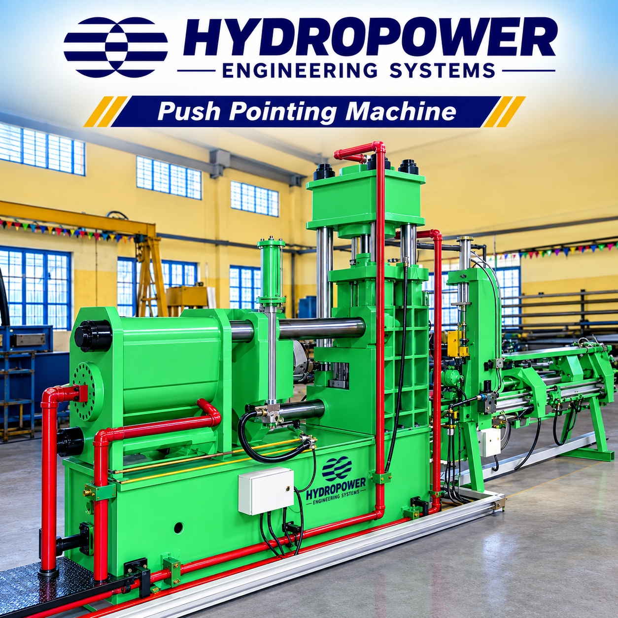 | Push Pointing Machine The Push Pointing Machine from Hydropower Engineering Systems is engineered to prepare tube ends for smooth and reliable drawing operations. View product → |
Frequently asked questions
Which rotor components are suitable for push pointing?
Suitable parts include tubular shafts, sleeves, housings, and drill-stem blanks when their material, diameter, wall thickness, length, and required end geometry fit the process.
Where does push pointing fit in the rotor manufacturing sequence?
It normally follows tube cutting, cleaning, and preparation, then precedes downstream forming, machining, joining, heat treatment, or inspection steps defined by the component drawing.
What production problems can push pointing solve or damage?
It can produce a reduced or shaped tube end for later assembly and improve repeatability, but poor setup can cause wall thinning, buckling, cracks, ovality, tool marks, or misalignment.
How should you compare push pointing equipment for earth drilling rotors?
Compare usable tube-size range, forming force, stroke, tooling access, alignment control, changeover time, measurement features, guarding, maintenance requirements, and proven sample results.
When does a manufacturer need a supplier’s process evidence?
Request process evidence when the part carries drilling torque or axial load, the material is difficult to form, tolerances are tight, or failure would require costly rework or field replacement.