
A suitable machine must do more than reduce a tube end: it must produce a repeatable geometry that enters the drawing die without snagging, buckling, or damaging the tube. By comparing forming capacity, tooling, material compatibility, automation, installation requirements, and acceptance-test data, you can distinguish a production-ready system from one that only meets a nominal diameter rating.
Key takeaways
- Confirm tube diameter, wall thickness, length, and pointed-end geometry before sizing.
- Test the material in cold, warm, and hot conditions before selecting a process.
- Compare forming force, die life, cycle time, and operator access—not price alone.
- Require sample parts and measured results in the supplier acceptance test.
What push pointing does—and how it differs from other end-preparation processes
Push pointing reduces a tube end by forcing it axially through a converging die or forming tool. The result is a reduced, tapered lead-in designed to enter a drawing die, not merely a sharp-looking tip.
- Load and align the tube with the die centreline.
- Clamp the tube without crushing its wall.
- Push the tube axially into the converging die.
- Form the reduced, tapered end.
- Withdraw the tube from the tool.
- Release the clamp.
- Transfer the pointed tube to the draw bench.
| Process | How the end is formed | Result |
|---|---|---|
| Push pointing | Axial force through a converging die | Tapered drawing lead-in |
| Rotary pointing | Rotating tools work the tube end | Rotationally formed reduced end |
| Draw pointing | A drawing operation pulls the end through tooling | Reduced end formed by drawing |
| Swaging | Radially reciprocating dies deliver repeated blows | Diameter reduction, often toward a solid end |
| Chamfering | A cutter removes material at an angle | Angled edge, without a drawing lead-in |
| Facing | A cutter removes material across the end | Square face |
| Hot upsetting | Heat and compression thicken or enlarge the end | Added wall thickness or enlarged end |
Choose the process by the next operation: a tapered lead-in, square face, chamfer, reduced solid end, or added wall thickness. An industrial pointing machine rated for solid bar is not automatically suitable for hollow tube; its dies, clamp, internal support, force path, and alignment must prevent wall collapse, ovality, and buckling.
Match machine capacity to tube dimensions and pointed-end geometry
A single maximum outside diameter does not define capacity. A thin-wall tube can collapse at a diameter the machine accepts, while a high-strength grade can exceed its forming force.
1. Request a capacity matrix for the tube push pointing machine, not a catalogue maximum. Require outside-diameter and wall-thickness ranges, maximum tube length, material grades and temper, yield or tensile-strength limits, and minimum and maximum pointed-end length.
2. Specify the point from the actual drawing-die entry: point length, included angle, nose diameter, transition length, and clearance. The nose must enter without snagging; the transition must avoid an abrupt shoulder that catches the die; clearance must prevent buckling while leaving enough material for reliable downstream gripping.
3. Require acceptance limits for concentricity, straightness, wall-thickness distribution, and ovality. A visually sharp point can still enter off-centre, reduce unevenly, or jam the die.
4. Define incoming-tube preparation for the push pointing equipment. Ends must be square-cut and burr-free; state the allowable ovality, weld-seam position and height, scale condition, laminations, and eccentric wall limits. Reject angular cuts, heavy scale, or defects that can split the point or damage the die.
5. Make the supplier prove the geometry on representative production samples, including the thinnest wall and strongest grade. Inspect point length, nose diameter, transition, surface tearing, and drawing-die entry; a go/no-go gauge will not reveal eccentric wall reduction or subsurface cracking.
Test material behaviour before choosing cold, warm, or hot pointing
A tube suits push pointing only after its forming behaviour matches the reduction schedule. Check the grade, yield strength, ductility, work-hardening rate, weld-seam condition, and tendency to gall or crack. Compare the diameter-to-wall-thickness ratio with trial data: collapse risk can require a mandrel, internal support, guide bush, or gentler reductions.
Poor seam orientation or uneven wall thickness creates an asymmetric point.
| Option | Benefit | Process penalty |
|---|---|---|
| Cold pointing | No heating system; clean dimensions | Raises local hardness and residual stress, and can reduce ductility |
| Warm pointing | Lower forming force for difficult grades | Requires controlled temperature, oxidation control, suitable lubrication, and repeatable heating |
| Hot pointing | Handles further-softened material | Adds scale, heat protection, temperature control, and operator-safety requirements |
Ask the push pointing machine manufacturer to trial production material, not a softer substitute. An industrial pointing machine that handles the force can still fail on metallurgical damage or wall collapse.
- Inspect the trial for surface and internal cracks, tearing, die marks, hardness increase, wall-thickness distribution, and internal folds.
- Require the supplier to state the lubricant name, application method, quantity or coverage, and temperature window. “Lubrication included” is not a process specification; poor control causes galling, pickup, contamination, or hidden defects.
- Reject the schedule if the pointed end buckles, loses concentricity, or fails to enter the drawing die. Use heat treatment or a different reduction route when cold work leaves inadequate ductility.
Compare force, tooling, cycle time, and operator access
Buy against peak forming force and complete cycle time, not motor horsepower. Entry force rises with material strength, reduction, friction, misalignment, and insufficient lubrication; a large motor does not prove the cylinder can form your tube.
- Request peak force, hydraulic pressure, cylinder stroke, motor power, clamp force, die-holder rigidity, guide arrangement, alignment adjustment, and force-monitor calibration.
- Specify pointing dies, mandrels or internal supports, guide bushes, clamps, die-change access, die material, bearing length, surface finish, and included spare wear parts.
- Ask how lubricant reaches the forming zone, then request die-life records and replacement intervals based on cycles or measured wear.
- Calculate loading and alignment, clamping, pressing, withdrawal, inspection, discharge, size changeover, and jam recovery. Pressing time alone hides lost production.
- Check foundation loads, footprint, centreline height, electrical supply, hydraulic connections, and loading and unloading clearance.
Manual loading costs labour but gives direct control; semi-automatic loading improves repeatability; automatic loading raises throughput only when alignment remains stable and changeovers stay simple.
| Loading mode | Advantage | Risk to check |
|---|---|---|
| Manual | Flexible for mixed sizes | Hand access and alignment variation |
| Semi-automatic | Faster repeatable handling | Feeder adjustment during changeover |
| Automatic | Lowest handling time | Jam recovery and tube damage |
Inspect fixed guarding, interlocks, visibility, hand access, and a safe method for removing stuck tubes. Compare the tooling package, not just the push pointing machine frame: a quotation without production dies, guides, supports, and wear parts does not define usable push pointing equipment.
Include the full cycle in your production model, including inspection and discharge. Then verify the pointed tube’s alignment after each changeover; poor support can create an off-centre point despite acceptable outside diameter.
Use a supplier acceptance test to protect the purchase decision
Approve a tube push pointing machine only after it has produced a repeatable batch from your own material, tooling, lubricant, and target cycle rate. Ask every push pointing machine manufacturer to run the same test, not a catalogue demonstration, and retain samples for dimensional and downstream inspection.
- Supply each bidder with the tube grades, outside diameters, wall thicknesses, production lubricant, representative dies, and intended cycle rate. Run enough consecutive pieces to expose drift, tool wear, and alignment loss rather than approving one attractive sample.
- Record peak forming force, hydraulic pressure, cycle time, size changeover time, point length, included angle, nose diameter, transition length, concentricity, straightness, wall-thickness distribution, surface condition, and die-entry performance.
- Push each point into the specified drawing die. Reject results that snag, buckle, crack, score, or require forceful correction; where possible, draw the sample and inspect the drawn surface, dimensional stability, and wall condition.
- Require the quotation to itemise production dies, mandrels or supports, guide bushes, clamps, lubricants, wear parts, controls, guards, foundation loads, utilities, calibration provisions, and spare-part lead times. Ask how force monitors are calibrated and how replacement tooling preserves alignment.
- Compare suppliers by repeatability, maintainable tooling, safe access, and documented performance across the actual tube range. Hydropower Engineers belongs in the same comparison when its customized hydraulic and tube-processing capability is measured against these results rather than catalogue horsepower alone.
Related product
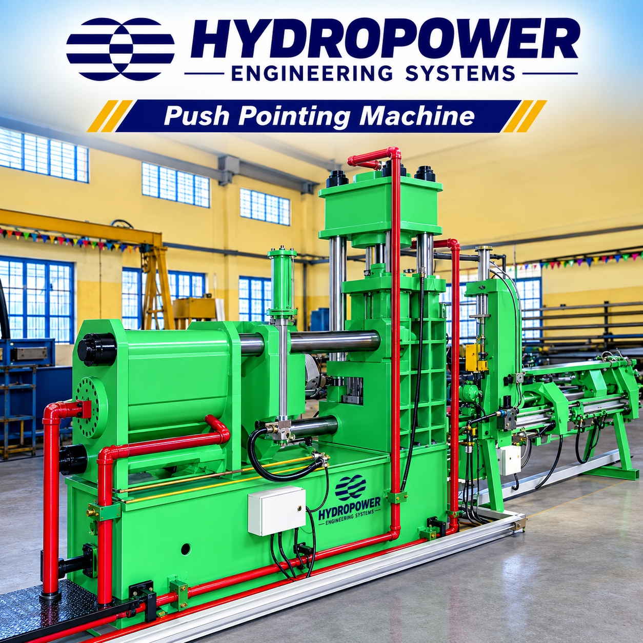 | Push Pointing Machine The Push Pointing Machine from Hydropower Engineering Systems is engineered to prepare tube ends for smooth and reliable drawing operations. View product → |
Frequently asked questions
What does push pointing do to a tube end?
It forces the tube axially through a converging die, creating a reduced tapered lead-in for entry into a drawing die.
How do you match a push pointing machine to a tube?
Check tube diameter, wall thickness, length, material strength, required reduction, and pointed-end geometry against machine capacity.
When should you use cold, warm, or hot pointing?
Test material behaviour first; choose the temperature range that forms the end without excessive force, cracking, scale, or dimensional loss.
What should you compare when choosing push pointing equipment?
Compare forming force, tooling design and life, cycle time, changeover effort, guarding, loading space, and operator access.
What belongs in a supplier acceptance test?
Specify sample tubes, pointed-end dimensions, surface and crack limits, cycle time, repeatability, tooling, and recorded force results.