
The correct edge preparation depends on what happens after cutting: a fitting, weld, flare, thread, seal, or forming operation each demands a different end condition. By the end, you will be able to match the workpiece, material, edge geometry, tooling method, inspection points, and production workflow to the application.
Key takeaways
- Match chamfer geometry to welding, sealing, fitting or forming requirements.
- Set cutting speed and feed for the material, diameter and wall thickness.
- Inspect chamfer angle, land, burrs and end squareness before production release.
- Validate clamping, tooling and repeatability across the full production batch.
Where Rod, Pipe and Tube Chamfering Applications Differ
Chamfering is required after cutting when an edge must stop cutting people, seals, fittings, or mating parts. Industrial rod pipe tube chamfering machine applications include burr removal, weld-bevel preparation, insertion lead-ins, thread starting, and ends prepared for flaring or swaging.
| Workpiece and job | Dimensional and material concern | Typical application |
|---|---|---|
| Rod | Solid steel or hardened surface; larger cutting load | Piston-rod seal entry, threading, welding, or a transition that will not score the rod seal |
| Thin-wall tube | Small wall thickness; collapse, ovality, or bell-mouthed bores | Hydraulic fittings, sleeves, flaring, and deburring without reducing ferrule engagement |
| Pipe | Diameter, wall thickness, root face, and bevel repeatability | Butt-weld preparation; ISO 9692-1 links joint preparation to material group, thickness, joint type, and welding process |
| Stainless or aluminium tube | Ductile chips, heat sensitivity, and surface damage | Clean assembly edges, instrument tubing, and corrosion-resistant process lines |
Diameter and wall thickness set the machine’s grip, tool reach, and allowable material removal. A general deburring setting cannot replace a pressure-pipe weld bevel: the latter must control bevel angle, root face, and end dimensions.
Likewise, an aggressive external chamfer can weaken compression or bite-type fitting engagement, while an excessive internal chamfer enlarges the unsupported sealing zone.
High-volume production favors dedicated tooling, automatic loading, chip control, and in-process checks; low-volume work favors adjustable tooling and quick changeover. Check internal edges as well as visible ones.
Rolled burrs, torn material, chatter, non-square ends, local wall thinning, and cutting-fluid contamination can pass a visual inspection, so use a chamfer or go/no-go gauge with periodic dimensional and cleanliness checks in tube end chamfering applications.
Choosing the Edge Form for Fittings, Welding and Forming
Choose the edge form by its downstream function: an external chamfer guides insertion, an internal chamfer removes the cutting hazard, and a welding bevel creates a joint geometry that a deburring pass cannot provide.
| Option | What it does | When to use it |
|---|---|---|
| External chamfer | Breaks the outside corner | Use for insertion into sleeves, seals, valves, or fittings; keep the chamfer small enough to preserve ferrule or sleeve engagement. |
| Internal chamfer | Removes the inside sharp edge | Use on hydraulic tubes to stop particles entering pumps, valves, and actuators; specify its size separately from the outside chamfer. |
| Double-end chamfer | Processes inside and outside edges | Use when one tube end needs both an insertion lead-in and contamination control. |
| Facing cut | Squares and cleans the end face | Use before flaring, swaging, compression fitting, or welding when end-face squareness matters. |
| Deburring operation | Removes loose, sharp, or rolled burrs | Use after cutting when the drawing requires a safe edge, not a defined material-removal profile. |
| Welding bevel | Removes material to form a controlled weld groove | Use for butt-weld preparation when the joint requires a specified bevel angle, root face, and land. |
For flared or compression fittings, do not let a general tube end chamfering application alter outside diameter, roundness, wall thickness, or face squareness. An industrial edge preparation machine set for insertion lead-in work is not automatically suitable for a pressure-pipe weld bevel; check the joint geometry against ISO 9692-1 and the welding procedure.
Setting Chamfer Geometry and Cutting Conditions by Material
Set chamfer angle and width from the next operation, not from the cutter. Use the drawing or process sheet for a weld bevel, including bevel angle, root face, and end dimensions; ISO 9692-1 links joint preparation to material group, thickness, joint type, and welding process.
For an insertion lead-in or deburring edge, specify the angle and width that let the fitting enter without leaving a scoring shoulder.
- Set facing allowance to the stock required to remove the saw cut, coating, or out-of-square end; excessive allowance wastes cycle time and reduces tube length.
- Set the burr limit as a measured maximum height, not “visually clean.” Check internal and external edges with a profile gauge, microscope, or tactile inspection method defined by the process sheet.
- Use a guided or workholding-controlled cutter when bore concentricity matters. A countersink can follow an off-centre bore and create a variable chamfer.
- Qualify speed, feed, coolant, tool nose geometry, and pass count on the actual wall thickness. Heavy wall may tolerate one pass; thin wall needs controlled engagement to prevent collapse and chatter.
| Material or condition | Tooling and cutting response | Qualification focus |
|---|---|---|
| Carbon steel, annealed | Carbide or high-speed-steel cutter matched to production rate | Confirm burr height and heat colour |
| Austenitic stainless steel | Sharp positive tool; maintain feed so the edge cuts rather than rubs | Check work-hardening, smearing, and tool wear |
| Cold-drawn, plated, or heat-treated tube | Use a supported, sharp tool and separate settings from annealed stock | Verify coating breakout, cracking, burr rollover, and dimensional change |
A rod pipe tube chamfering machine is therefore set by the specified edge function, while an industrial edge preparation machine must prove repeatability across each material and wall condition.
A Controlled Workflow for Accurate Tube-End Preparation
A reliable end-preparation cycle controls the part before it controls the cutter. Across rod pipe tube chamfering machine applications, match the workholding method to the outside diameter, wall thickness, material and required edge form; a thin-wall tube needs support that a solid rod does not.
1. Verify the drawing or process sheet, then inspect the cut end for excessive burrs, distortion and damage. Reject material that cannot seat squarely.
2. Clean the tube, jaws and support mandrel. Set a collet, soft jaws or expanding fixture that grips without crushing the wall; excessive clamping creates ovality and slippage.
3. Insert the workpiece to a fixed stop and align its axis with the spindle. Confirm that the end contacts the stop evenly, or facing will leave an out-of-square surface.
4. Set cutter projection, chamfer width, angle, facing allowance and depth stop. Use a sharp tool with adequate clearance; a blunt or poorly supported cutter promotes chatter, rolled burrs and a bell-mouthed bore.
5. Start at the specified speed and feed, allowing the cutter to enter steadily. Stop if vibration, rising heat or discoloration appears; reduce overhang or cutting load rather than forcing the pass.
6. Retract the tool before releasing the part. Remove chips with a brush or vacuum, not bare hands or compressed air directed into a hydraulic passage.
7. Check the face, internal and external edges, bore, chamfer gauge and burr height. For flared tubes, confirm the square, burr-free end against the flare-tool maker’s requirements; chamfering equipment does not replace controlled flaring.
Guarding, chip containment and interlocked access must remain effective during loading, tool changes and jam clearing. Good pipe chamfering equipment prevents contamination from becoming a downstream leak or weld defect.
Validating Equipment for Repeatable Production
Reject any pipe chamfering equipment that shows only a sharp-looking edge. For butt-weld preparation, verify repeatable bevel angle, root face, chamfer width, end squareness, and internal-external concentricity against the drawing and ISO 9692-1 joint-preparation requirements.
Ask the supplier to demonstrate these controls:
- Diameter and wall-thickness range, including the smallest bore that the internal tool can enter without deflection.
- Fixture accuracy, clamping pressure, cutter adjustment, facing allowance, cycle time, and tool-life records.
- Measured results from at least 30 consecutive parts, with bevel angle, root face, burr height, and end squareness recorded.
- Guards around rotating cutters, chip containment, interlocked access, and safe procedures for loading, tool changes, and jam clearing.
Use application tests that match the actual downstream operation.
| Application | Verify in the test | Reject when |
|---|---|---|
| Deburring | Burr height, scratches, chips, and edge consistency | A countersink follows an off-centre or oval bore |
| Weld bevel | Bevel angle, root face, concentricity, and repeatability | The machine produces a visual bevel but misses dimensions |
| Flare preparation | Square face, burr-free edge, and unchanged wall thickness | A rolled burr or angled face creates an asymmetric flare |
| Insertion lead-in | Lead-in width, surface finish, and fit with the sleeve | Parts bind or show excessive clearance |
A rod, pipe and tube chamfering machine configured for thin-wall deburring is not automatically an industrial edge preparation machine for structural or pressure-pipe welds. Hydropower Engineers can be included in a supplier comparison when its test pieces are measured against your drawings, tooling requirements, and production volume rather than judged from photographs.
Related product
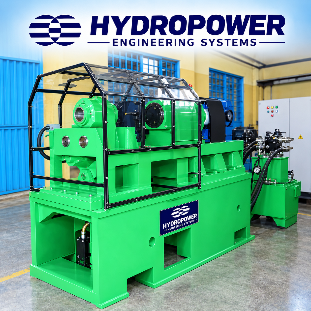 | Edge Preparation Machine Hydropower Engineering Systems offers a robust and precision-engineered Pipe Chamfering Machine / Edge Preparation Machine, developed for efficient... View product → |
Frequently asked questions
How do rod, pipe and tube chamfering applications differ?
Rod chamfering focuses on solid round stock, while pipe and tube preparation must account for wall thickness, bore protection, end squareness and deformation risk.
Which edge form should you choose for fittings, welding and forming?
Use a small deburring chamfer for handling and insertion, a defined bevel for welding, and a controlled lead-in or radius when the end will be flared, swaged or formed.
How do you set chamfer geometry and cutting conditions by material?
Set the angle, chamfer width or land, spindle speed and feed according to material hardness, diameter, wall thickness, tooling and the required downstream joint.
How do you validate a rod, pipe or tube chamfering machine for repeatable production?
Check clamping, tool alignment, end squareness, chamfer dimensions, burr formation and sample consistency before approving the machine for batch production.