A manifold controls where hydraulic oil goes, while a bell housing establishes and protects the mechanical connection between a prime mover and a pump or motor. By the end, you will be able to trace a working circuit, distinguish these parts from similar components, and specify the dimensions, flow data, and service provisions needed for reliable integration.
Key takeaways
- Match manifold passages and valves to required flow and pressure.
- Specify ports, pilot circuits, filtration, and access before machining.
- Use the bell housing to maintain shaft alignment and contain hazards.
- Leave room to remove valves, hoses, couplings, and guards during service.
What Each Component Does in a Working Machine
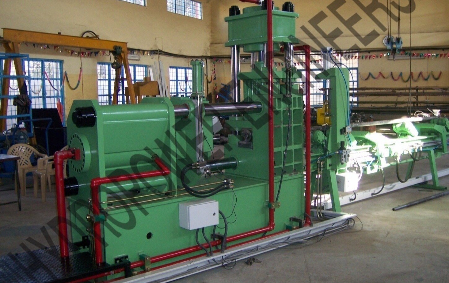
Manifolds and bell housings in special purpose machines solve different problems. A hydraulic manifold is a machined block with drilled passages, valve cavities, and ports. In one tube-processing machine, it receives pressure oil from the pump, directs it through directional and pressure-control valves, sends pilot flow where needed, and returns oil to the tank.
Its passages connect the working functions without long external hose runs.
The manifold also helps enforce the machine’s operating sequence. Integrated checks or load-holding valves can stop an actuator from moving when pressure falls, while test points and isolation provisions let technicians commission and troubleshoot the circuit.
The trade-off is hidden complexity: a plugged drilling or machining error inside the block is harder to locate than a visible hose fault.
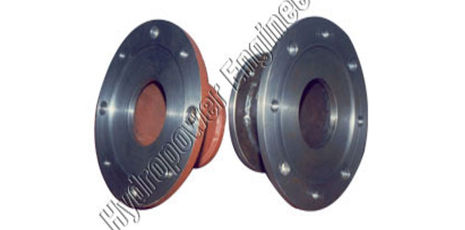
A bell housing performs the mechanical connection. It adapts the drive motor to the hydraulic pump, uses pilot registers and flange dimensions to hold their shafts concentric, and encloses the flexible coupling as a guarded motor-pump module. The coupling transmits torque but cannot correct substantial misalignment; poor alignment damages seals and bearings.
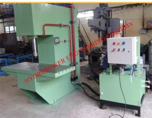
Together, these components make special purpose machine hydraulics compact: the bell housing packages the power source, while the manifold controls the work circuit. Keep the manifold near its valves and actuators, but leave clearance for cartridge removal, fitting access, test-point inspection, and pump-seal or coupling service.
How the Manifold Routes Oil and Replaces External Plumbing
A manifold routes pump pressure, actuator return, and pilot flow through drilled, intersecting passages in one machined block, so much of the tubing between the power unit, valves, and actuators disappears. Ports connect the block to the pump, tank, actuators, and test points; valve cavities hold directional and pressure-control valves, including cartridge designs.
- Pressure flow enters from the pump and reaches a directional valve, which sends oil to the required actuator.
- Return flow leaves the actuator, passes through the return passage and filtration path, and goes back to the tank.
- Pilot flow feeds a control or cartridge valve, allowing a small signal to switch larger flow or sequence the next motion.
This arrangement suits hydraulic manifold applications where several functions share a compact power unit and must operate in a defined sequence. Short internal passages reduce hose volume, fitting count, leak points, snag hazards, and installation space.
It is especially useful in special purpose machine hydraulics when the manifold can sit close to the working valves or actuators.
Choose it over separately mounted valves and pipework when flow paths are stable, the layout repeats, and high flow demands a compact cartridge-valve package. Use external piping or a remote valve panel when functions change frequently, fault-finding access matters more than compactness, or internal damage would be difficult to repair.
Size every passage for maximum simultaneous flow. A block that works during single-axis motion can overheat or slow the machine when two functions operate together. For accumulators or vertical loads, include isolation, a controlled dump path, pressure indication, and lockout instructions; a bleed port alone does not prove trapped oil is safe.
What to Specify for Flow, Valves, Safety, and Maintenance
Specify the operating envelope before drawing a cavity: maximum and continuous flow for each function, pressure at the actuator, oil viscosity and temperature, and the sequence for clamping, feeding, advancing, rotating, ejecting, and tool return. Undersize passages create pressure drop and heat; oversized valves waste space and can make low-flow control unstable.
Include pump, return, and pilot flows, not only the pump rating.
For cartridge-valve manifolds, record the cavity standard, cartridge size, pilot ratio, spring range, cracking pressure, and cover function. A similar-looking cartridge can reverse a sequence or eliminate load holding. Across hydraulic manifold applications, match cross-port reliefs, counterbalance valves, checks, and shuttle valves to the load and its failure mode.
Specify these safety and service provisions:
- An isolation valve and controlled dump path for accumulators, vertical loads, and trapped pilot pressure.
- Pressure gauges or test points at pump, actuator, and pilot circuits.
- Lockout instructions that identify every stored-energy volume; a manual bleed port alone is not proof of safe depressurization.
- Removable cartridges, labelled ports, accessible plugs, and clearance for tightening fittings without removing the block.
- Clean-out and flushing provisions, plus a schematic showing cavity numbers, valve part numbers, settings, and torque values.
For manifolds and bell housings in special purpose machines, leave access around both the hydraulic block and drive assembly.
| Option | Main advantage | Main service trade-off |
|---|---|---|
| Custom integrated block | Compact, few leak paths | Modifications can require a new block |
| Cartridge manifold | High flow and combined logic | Exact cavity and cartridge matching is critical |
| Modular valve stack | Easier circuit changes | More interfaces, height, and leakage points |
How a Bell Housing Aligns and Protects the Drive Assembly
A pump can bolt to a motor and still destroy its seal if the shafts are not concentric. A bell housing establishes the motor-to-pump relationship, locates both parts through pilot registers and flange faces, and encloses the flexible coupling. The coupling transmits torque but tolerates only limited residual angular or parallel misalignment.
SAE J744 flange and shaft conventions commonly define hydraulic interfaces, although metric and manufacturer-specific dimensions also exist. The standard does not confirm that the housing, coupling, motor, and pump have adequate torque capacity. Check these details before ordering:
- Motor frame, flange, and shaft dimensions
- Pump mounting standard and pilot diameter
- Coupling bore, length, torque rating, and speed
- Axial clearance, orientation, and pump weight support
- Base alignment and access to the pump seal and coupling
A bell housing is not an adapter plate with a larger cover. It is a precision locating and protective structure. Bell housing industrial equipment uses it to create a compact, guarded drive module; manifold bell housing applications still require separate attention to valve access, trapped hydraulic energy, and service clearance.
| Part | Primary function | Limitation |
|---|---|---|
| Bell housing | Aligns and encloses motor-pump coupling | Does not correct poor base alignment |
| Adapter plate | Changes a bolt pattern or mounting face | Does not necessarily locate shafts precisely |
| Coupling guard | Prevents contact with rotating parts | Does not establish concentricity |
| Gearbox housing | Supports gears and transmits changed speed or torque | Does not automatically suit a direct pump drive |
How to Integrate Both Parts Without Creating Service Problems
Place the manifold near the valves and actuators it serves, while keeping the bell housing at the motor-pump assembly. This arrangement shortens hose runs without blocking coupling, pump-seal, cartridge, or test-point access. In special purpose machine hydraulics, compactness is useful only when technicians can remove parts without dismantling the machine.
1. Map every function in sequence: clamping, feeding, advancing, rotating, ejecting, and tool return. Mark pressure, return, pilot, drain, and isolation points on the circuit diagram. Add checks, counterbalance valves, or pilot-operated valves where pressure loss could let an actuator move unexpectedly.
2. Select the bell housing and coupling as a matched set. Check SAE J744 flange and shaft dimensions, coupling torque capacity, shaft alignment, rotation, and thermal clearance; the flange standard alone does not prove compatibility. Keep the coupling guard removable.
3. Reserve working clearance around cartridge covers, fittings, gauges, electrical connectors, and filter elements. A custom block saves space, while a modular stack makes later changes easier but adds interfaces and leak paths.
4. Test each function at controlled pressure before production trials. Record leakage, sequence timing, relief settings, actuator motion after pump shutdown, and every test-port reading. Correct a machining or plugging error before the manifold is installed behind guards.
5. Deliver an as-built drawing identifying port names, cavity standards, cartridge part numbers, hose sizes, torque values, and bell-housing dimensions. Hydropower Engineers can use that record when building manifold bell housing applications for bell housing industrial equipment, preventing a visually similar replacement from altering the circuit.
Related product
 | Special Equipments Hydropower Engineering Systems specializes in the design and manufacture of high-precision Manifolds and Bell Housings, engineered for seamless... View product → |
Frequently asked questions
What does a hydraulic manifold do in a special purpose machine?
A hydraulic manifold receives pump flow, routes oil through directional and pressure-control valves, supplies pilot circuits, and returns oil to the tank through drilled internal passages.
What should you specify for a hydraulic manifold?
Specify operating pressure, peak pressure, flow rate, valve functions, port sizes, fluid type, filtration, pilot circuits, safety controls, test points, and access for maintenance.
What does a bell housing do in industrial equipment?
A bell housing connects and protects the motor, pump, gearbox, or other drive components while maintaining shaft alignment and containing rotating parts.
How do you integrate manifolds and bell housings without service problems?
Provide access for valve removal, hose and coupling inspection, alignment checks, drain and bleed points, protective guards, and enough clearance for tools and replacement parts.