A pipe end can look clean while still being out of square, carrying a burr, or presenting the wrong land width for welding or assembly. You will learn how to distinguish each preparation operation, measure the result, compare machine types, and decide whether a dedicated system suits your production mix.
Key takeaways
- Match facing, chamfering, beveling, or deburring to the defect.
- Control feed rate, tool geometry, and clamping to improve repeatability.
- Specify tolerances, surface finish, and acceptance samples before ordering.
- Choose machine finishing over grinding when volume and consistency justify it.
What Edge Preparation Removes—and Which Operation You Actually Need
Facing removes material across the pipe end to correct an out-of-square cut and create a flat reference face. The other operations target different defects; choosing the wrong one can leave poor fit-up or damage a sealing surface.
| Operation | What it does | Defect it corrects |
|---|---|---|
| Facing | Machines the end face perpendicular to the pipe axis | Saw-cut angle, uneven end height, poor seating and excessive runout |
| External chamfering | Cuts an angle on the outside edge | Sharp outside corner, raised burr and interference during insertion or assembly |
| Internal chamfering | Cuts an angle on the bore-side edge | Internal burr, restricted bore entry and damage to seals, tubes or fittings |
| Deburring | Removes loose, raised or sharp metal without defining a major angle | Saw burrs, filing slivers and handling hazards |
| Beveling | Removes more material at a specified angle to form a weld groove, often with a controlled root face | Inconsistent weld angle, missing land and inadequate root access |
An edge preparation machine for pipes improves consistency by holding the pipe and cutter in a fixed relationship, but a chamfer for a fitting is not automatically a weld preparation. Confirm the weld procedure’s bevel angle, root face and root gap before cutting; these dimensions control penetration and filler volume.
Likewise, use the geometry specified for a flare, cone, bite-type fitting or face-seal connection rather than assuming a weld bevel will seal. Inspect end squareness, radial runout, burr removal and surface damage separately.
How a Controlled Pipe-End Process Improves Repeatability
Repeatability comes from controlling the entire cycle, not from cutting a chamfer quickly. An industrial pipe finishing machine must locate each pipe from the same datum, hold it securely, and guide the tool to dimensions set by the drawing or qualified welding procedure.
- Cut the pipe, then remove scale and loose debris from the end.
- Load the workpiece and locate its length against a fixed stop or programmed datum.
- Clamp it without crushing a thin wall or allowing the pipe to rotate eccentrically.
- Bring the facing, chamfering, or beveling tool into the end under a controlled feed.
- Complete the cut, stop the spindle, and remove chips with a brush, hook, or guarded chip system—not bare hands.
- Inspect the end, release the clamp, and unload only after rotation has stopped.
Measure a sample from the first article and throughout the batch. The key checks are:
| Bevel angle | Measure with a bevel gauge or optical system | Confirms groove geometry and root access |
|---|---|---|
| Root face or land width | Measure with a calibrated rule, microscope, or profile gauge | Controls penetration and filler-metal volume |
| End squareness | Check face-to-pipe-axis deviation around the circumference | Prevents uneven root gaps during fit-up |
| Radial runout | Rotate the pipe and record indicator movement at the finished end | Reveals eccentric clamping or misaligned tooling |
| Surface condition | Record burrs, tearing, chatter, and tool marks | Identifies defects that can obstruct assembly or welding |
Consistent measurements reduce welder adjustment, but they do not correct ovality, contamination, high-low misalignment, or an excessive root gap.
How to Specify the Machine and Run a Meaningful Acceptance Test
Specify the machine against your actual pipe grades, outside diameters, wall thicknesses, cut lengths, and batch sizes—not a demonstration tube. Define the required operation, material removal, bevel angle, land width, face squareness, radial runout, burr condition, and maximum allowable dimensional drift.
| Production profile | Suitable configuration | Main acceptance risk |
|---|---|---|
| Short runs, frequent sizes | Flexible manual or semi-automatic clamping and quick tooling change | Changeover consumes the claimed cycle-time saving |
| Repeat batches, several diameters | Automatic locating, dedicated inserts, and recorded offsets | Tool wear shifts land width or angle during the batch |
| High-volume, stable product mix | Automatic loading, clamping, chip removal, and inspection points | Nominal throughput collapses if swarf clearing or intervention is slow |
Specify cutter or insert grades for each pipe material, spare-tool availability, clamping range, maximum pipe length and weight, motor capacity, and the complete cycle time from loading to unloading. For pipe edge preparation equipment bangalore buyers, local insert supply, training, calibration support, and breakdown response belong in the specification.
Require fixed or interlocked guards, emergency stopping, secure workholding, and safe chip removal.
Run first-article trials with production material and at least three sizes, including the thinnest wall and the largest diameter. Record:
- Pipe identification, heat or batch number, material, dimensions, and cutting method.
- Tool identity, insert condition, offsets, coolant, cycle time, and operator interventions.
- Bevel angle, land width, face squareness, radial runout, burr height, and surface condition.
- Measurements from the first parts, mid-batch parts, and final parts.
- Changeover time, rejected parts, rework, chip interference, and stoppages.
- Guarding, emergency-stop operation, and the permitted tool-wear limit.
When Machine Finishing Beats Grinding—and When It Does Not
A dedicated machine wins when the same pipe end must leave the process with the same angle, land width, and squareness. Grinding remains sensible for repair work, prototypes, and short runs where setup time costs more than operator labour.
| Option | Repeatability and labour | Setup, flexibility, safety, and capital cost | Best use |
|---|---|---|---|
| Handheld grinder | Lowest repeatability; high operator effort and rework | Fast to start, highly flexible, but sparks, dust, kickback, and hand fatigue increase risk; lowest capital cost | Repairs, awkward locations, and very short runs |
| Bench grinder | Better support than handheld grinding, but still operator-dependent | Moderate setup and cost; limited pipe diameter and handling flexibility; exposed abrasive wheel requires guarding | Small parts and light deburring |
| Manual lathe | High potential accuracy, with skilled labour and inspection | Long loading and setup; flexible for varied sizes; higher existing-machine and labour cost | Low-volume work needing controlled facing or chamfering |
| Dedicated beveling machine | High repeatability and lower labour after setup | Moderate-to-high capital cost; size changes require tooling, clamping, and parameter changes; enclosed cutting improves safety | Repetitive batches and controlled weld preparation |
| Finished-end cutting machine | Consistent cut and finish in one cycle | Highest integration and capital cost; less flexible when materials, diameters, or lengths change | High-volume production with stable part families |
To judge edge preparation machine benefits in Bangalore division, measure tool-change time, chip removal, inspection, and breakdown response—not only the catalogue cycle. Hydropower Engineers is worth evaluating only after confirming local cutter availability, operator training, calibration support, and service response for your actual sizes and materials.
Local support beats a faster cycle when one stoppage delays an entire batch.
Related product
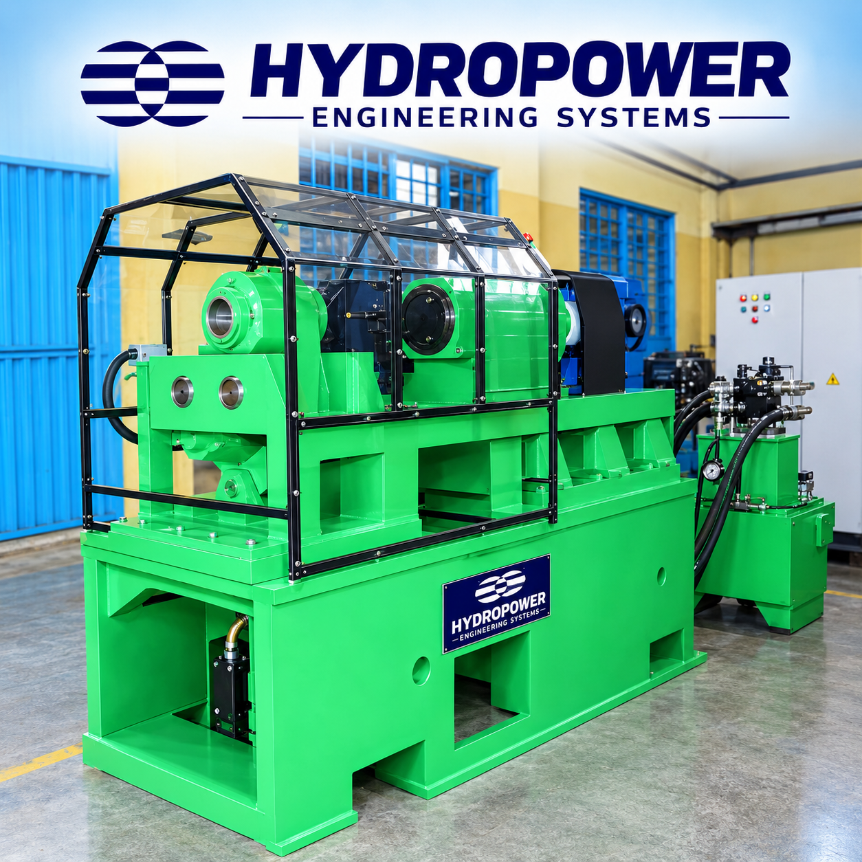 | Edge Preparation Machine Hydropower Engineering Systems offers a robust and precision-engineered Pipe Chamfering Machine / Edge Preparation Machine, developed for efficient... View product → |
Chamfer Geometry Is Not the Same as Weld Preparation
A chamfer supports assembly when it removes a burr, creates a lead-in, or helps a pipe enter a fitting, seal, thread, flare, cone, bite-type fitting, or face-seal connection. That geometry is not automatically suitable for welding; excessive facing can reduce thin-wall tube below the required wall or land.
For welding, use the drawing and qualified welding procedure specification (WPS), not a generic machine setting. Bevel angle, root face, root gap, end squareness, and fit-up jointly control root access, penetration, groove volume, and filler-metal consumption. ASME B16.25 gives butt-welding-end preparation dimensions, but it does not qualify the WPS or guarantee weld quality.
Use this decision procedure:
- Identify the operation: assembly, sealing, or welding. For welding, record the specified bevel angle, root face, root gap, wall thickness, and internal machining requirement.
- Inspect the first article with calipers, an angle gauge, and a squareness check. Measure remaining wall, land width, bevel angle, and end squareness; a diameter go/no-go check cannot reveal a lost root face.
- Check fit-up with the actual mating pipe and fixture. Reject a preparation that forces excessive gap correction, misalignment, or welder adjustment.
- Recheck inserts and cutters during the batch. Tooling wear changes the land and angle; unmanaged chips can damage the finish or obstruct clamping.
- Select equipment with enclosed guarding, chip control, operator training, calibration support, and replacement tooling. The pipe chamfering equipment benefits disappear when unsafe access, frequent clearing, or slow service interrupts production.
Frequently asked questions
What does an edge preparation machine remove from a pipe end?
Facing removes material across the end to correct an out-of-square cut. Chamfering removes a corner, while deburring removes sharp burrs without creating a weld bevel.
How does controlled pipe-end machining improve repeatability?
Rigid clamping, controlled feed, consistent tool geometry, and defined dimensions produce more uniform pipe-end geometry across batches.
What should you include in a machine acceptance test?
Specify pipe dimensions, material, required bevel or chamfer geometry, dimensional tolerances, surface finish, cycle time, and inspection records before testing.
When is machine finishing better than grinding?
Machine finishing suits repeat production requiring consistent geometry and cycle times. Grinding remains practical for repairs, isolated parts, irregular shapes, or difficult on-site access.