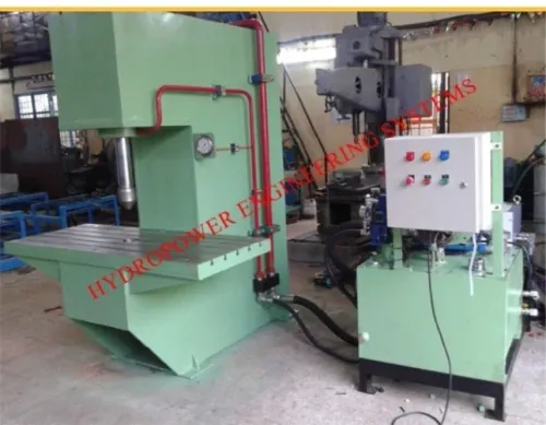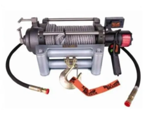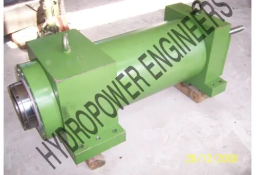
Inconsistent swaged parts usually result from a material change, worn tooling, poor centring, unstable hydraulics, incorrect settings, or a combination of these factors. You will be able to isolate the cause, measure the defect correctly, run a controlled trial, and define the records and service checks needed to prevent recurrence.
Key takeaways
- Contain the suspect lot and record heat, grade, dimensions, hardness and surface condition.
- Map each defect to its position, timing and direction before changing settings.
- Match centring, tooling, lubrication and hydraulic checks to the material and tube size.
- Define dimensional limits, test frequency and records before requesting machine service.
Separate Incoming-Material Variation from Machine Repeatability
Contain the suspect lot before changing the setup. Record each tube or rod’s heat number, material grade and condition, outside diameter, wall thickness, hardness, straightness, seam orientation, initial ovality, mill scale, corrosion, and lubrication condition.
Without this traceability, pipe swaging machine problems in Bangalore Division can look like hydraulic faults when the heat is the real variable.
Compare several pieces from the suspect lot with several pieces from a previously accepted lot. Run both through one qualified setup without changing pressure, speed, feed length, stroke, clamping, tooling, or lubricant.
| Result | Likely source | Next check |
|---|---|---|
| The defect follows one heat number | Material variation, prior cold work, or work hardening | Check hardness before and after swaging, reduction history, and whether an intermediate anneal is required |
| The defect repeats across different lots | Machine repeatability or common tooling condition | Inspect dies, guides, clamping, alignment, runout, and control inputs |
| Only some pieces fail within one lot | Incoming dimensional or surface variation | Recheck diameter, wall thickness, straightness, ovality, scale, corrosion, and lubrication |
Record every measurement against the drawing or control plan, including the actual location and limit for each dimension. Do not write only “out of size”; identify whether the failure is outside diameter, wall thickness, taper, ovality, swage length, or another defined characteristic.
Read the Defect Pattern Before Changing a Setting
A defect’s location and shape usually identify the cause faster than a pressure adjustment. Record each pipe swaging defect by axial position and clock position, including lobing, scoring, cracks, wrinkles, bellmouth, end flare, taper, a nonuniform transition radius, and misaligned ends.
| Defect pattern | Likely cause | Check before changing settings |
|---|---|---|
| Taper or end flare | Unequal closure, feed error, or die alignment | Compare entry, middle, and exit diameters |
| Lobing or scoring | Die wear, chipped corners, pickup, uneven polishing, or mismatched segments | Inspect every die face and assembled forming cavity |
| Wrinkles or bellmouth | Poor support, excessive reduction, or unstable centring | Check mandrel, clamping, projection, and reduction per pass |
| Longitudinal crack or split | Hard material, prior cold work, excessive reduction, poor lubrication, or die damage | Check hardness, work-hardening history, lubrication, and die condition |
Measure outside diameter at the entry, middle, and exit of the swaged length. Take readings on two perpendicular axes or at several clock positions; calculate ovality as maximum diameter minus minimum diameter, not from one caliper reading.
Inspect wall thickness at multiple angular positions with a micrometer, ultrasonic gauge, bore gauge, or another suitable method. Do not infer wall thickness from outside diameter. If a part passes the first reduction but cracks later, check material hardness and required intermediate anneal before raising hydraulic pressure.
Replace matched die segments together when unequal closure or circumferential variation repeats.
Verify Material-Specific Setup, Centring and Tooling
Many rod pipe tube swaging machine problems come from applying one setup to different workpieces. Treat solid rods, hollow pipes, and tubes as separate processes before investigating deeper machine faults.
| Workpiece | Setup focus | Failure if mismatched |
|---|---|---|
| Solid rod | Rod-specific die geometry, feed support, reduction per operation, passes, and lubricant | Taper, scoring, bending, or excessive load |
| Hollow pipe | Die profile, internal support decision, reduction schedule, and clamping | Collapse, ovality, wrinkles, or unstable wall thickness |
| Tube | Mandrel fit, insertion depth, die centre, lubrication, and wall control | Mandrel seizure, galling, thinning, or dimensional drift |
Check the die profile, die material, reduction per operation, number of passes, lubrication compatibility, expected tool life, and changeover condition against the part drawing and material grade. Many rod pipe tube swaging machine problems are actually worn, chipped, undersized, or incorrectly matched tooling.
Inspect the assembled dies, guides, clamps, chucks, mandrel, bearings, spindle, die-holder, and feed unit. Measure runout and concentricity with production clamping and support in place; an empty-machine check can hide misalignment.
- Set rod or tube projection, die centre, clamping force, feed-stop position, stroke length, and mandrel insertion depth from the qualified process sheet.
- Inspect the mandrel for galling, undersizing, bending, and seizure risk; measure inside diameter and wall thickness separately.
- Repeat the approved warm-up routine, run a short trial, and change only one variable at a time. Record the die and mandrel numbers, material grade, lubricant, and result.
Troubleshoot Lubrication, Hydraulics and Operator Inputs in Order
1. First verify the latest changes: material heat, die condition, feed length, stroke, pressure, speed, dwell, clamping, and lubricant. A setting copied from an older setup record can produce different geometry with worn tooling or a changed material condition.
2. Check the lubricant type, concentration or viscosity, delivery location, flow rate, cleanliness, and compatibility with the material. Use this comparison before adding more lubricant:
| Condition | Likely effect | Check |
|---|---|---|
| Excess lubricant | Slipping or contaminated gripping zone | Inspect clamp contact and wipe-off |
| Insufficient lubricant | Scoring, pickup, high load, temperature rise | Inspect die marks and confirm delivery flow |
| Wrong or dirty lubricant | Erratic feeding or material reaction | Verify specification and contamination |
3. Trend commanded and actual pressure, flow, cylinder position, cycle time, oil temperature, filter differential pressure, valve response, and pressure stability during the forming stroke. Inspect the pump for wear, cylinders for internal leakage, oil for aeration, the proportional valve for sticking, seals for degradation, and viscosity for temperature-related change.
4. Check pressure gauges against a calibrated reference. Then inspect sensors and limit switches for incorrect stroke termination or feed position.
Run a controlled trial on a small sample after these checks. Change one input at a time; changing pressure, speed, and feed together destroys the evidence needed for swaging machine troubleshooting. Record each result against the drawing or control plan.
Define the Acceptance Record and Choose the Right Service Scope
Do not release production until the service decision produces a signed acceptance record and a capability trial using your actual rod or tube. A pressure reset is not acceptance: it cannot prove correct geometry, tooling condition, alignment, or material response.
| Tooling choice | Option A | Option B |
|---|---|---|
| Die profile | Single profile matched to the finished form | Staged profiles for difficult transitions or lower reductions per pass |
| Reduction schedule | One-pass reduction where load and material permit | Multiple passes where cracking, thinning, or distortion appears |
| Die material | Select for workpiece hardness, load, and wear risk | Select a different grade or treatment when pickup or short tool life is proven |
| Lubrication compatibility | Confirm with the specified lubricant and workpiece | Reject if it causes scoring, slipping, pickup, or contamination |
| Changeover time | Shorter, but only useful for repeat production | Longer, justified by stability across sizes or materials |
| Expected tool life | Record evidence from comparable duty | Require a documented life estimate and inspection interval |
Approve the setup record only when it identifies:
- Material grade and condition, heat number, starting and finished dimensions
- Die and mandrel numbers, lubricant specification, feed rate, stroke, cycle settings, and warm-up routine
- Inspection equipment, sampling frequency, and limits for outside diameter, inside diameter, wall thickness, length, taper, ovality, and swage location
For industrial swaging machine service bangalore, demand die and mandrel inspection, spindle and guide alignment, feed calibration, hydraulic pressure and flow verification under load, oil contamination checks, and sensor and limit-switch tests. Hydropower Engineers is worth considering only when it provides this documented scope and signs the trial results against your drawing or control plan.
Related product
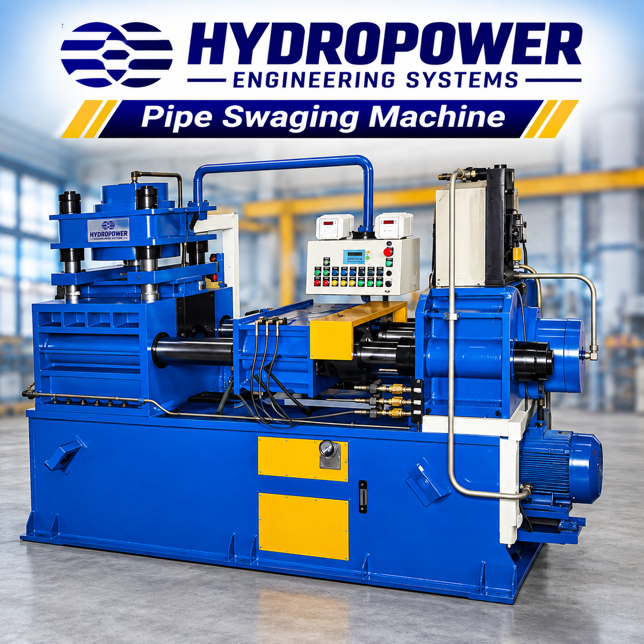 | Pipe Swaging Machine Hydropower Engineering Systems manufactures robust and efficient Pipe Swaging Machines designed to reduce the diameter of pipes and solid rods to the... View product → |
Frequently asked questions
How do you separate incoming-material variation from machine repeatability?
Contain the suspect lot, then record each tube or rod’s heat number, grade, condition, outside diameter, wall thickness, hardness, straightness, seam orientation, initial ovality, mill scale, corrosion and lubrication condition. Compare repeated parts from the same setup with parts from different material lots.
What should you check before changing a swaging-machine setting?
Read the defect pattern first. Record whether the defect appears at the entry, transition or exit, whether it repeats around the circumference, and whether it follows one tool, station, operator or material lot.
Which setup checks help prevent pipe swaging defects?
Verify that the setup matches the material and tube size. Check centring, die or tooling condition, alignment, tool clearance, starting dimensions and the workpiece’s seam orientation before adjusting force or stroke.
What is the correct order for swaging machine troubleshooting?
Check lubrication and workpiece condition, then inspect hydraulic pressure, flow, leaks and repeatability, and finally review operator inputs such as loading, alignment, stroke selection and cycle timing.
What should an acceptance record for industrial swaging machine service include?
Define the measured dimensions, ovality limit, surface criteria, test quantity, material heat or lot, setup values, hydraulic readings, tooling identification and pass-fail results. Use those records to choose setup support, repair, overhaul or replacement scope.